


53
Test Procedures: (Contacts)
1. Disconnect the dispenser from the power source.
2. Disconnect the WHI/VIO and WHI/YEL wires. Con-
nect an ohmmeter across the two coil terminals
where the wires were just removed.
3. Connect the dispenser from the power source..
4. Turn on Power (I/O) Switch. Verify the dispenser
is in the “DAY” mode.
The indication must be:
a) continuity in the “DAY” mode,
b) open in the “NIGHT” mode.
If continuity is present as described, the Relay is op-
erating properly.
If continuity is not present as described, replace the
Relay.
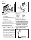
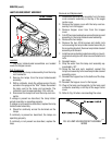
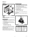
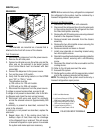
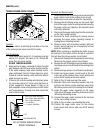
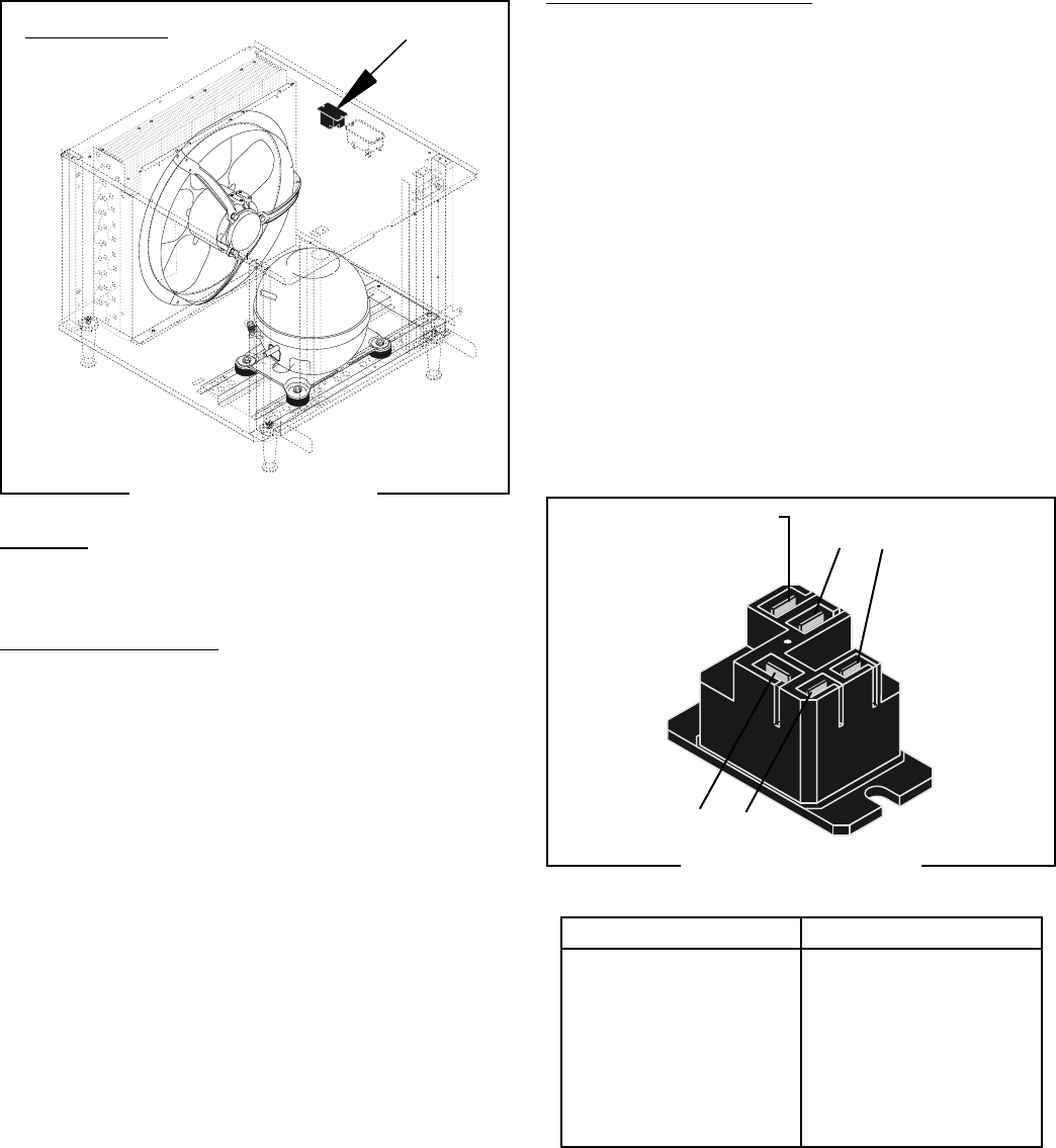
FIG. 52 LAMP RELAY
SERVICE (cont.)
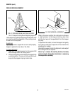
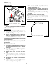
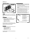
LAMP RELAY
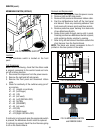
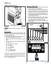
FIG. 51 LAMP RELAY
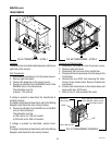
Location:
The Lamp Relay is located under the upper deck of
the chassis, on the right side.
Test Procedures: (Coil)
1. Disconnect the dispenser from the power source.
2. Connect a voltmeter, across BLU/BLK wire (+) and
the VIO wire (-).
3. Connect the dispenser from the power source.
4. Turn on Power (I/O) Switch. Verify the dispenser
is in the “DAY” mode.
The indication must be:
a) 12 volts dc in the “DAY” mode,
b) 0 volts dc in the “NIGHT” mode.
If voltage is present as described, the Control Board is
operating properly. Replace Relay if it does not energize
when voltage is present.
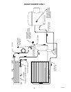
If voltage is not present as described, refer to the Wiring
Diagrams and check the main wiring harness.
If harness has continuity, replace the Control Board.
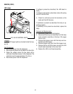
ULTRA-2 shown
R
Not Used (N/C)
3 1
4 2
1. (-) 12vdc (VIO) from
Control Board J5-7
2. (+) 12vdc (BLU/BLK) to
Control Board J5-19
3. 12vac (WHI/VIO) to
Lamp Connectors
4. 12vac (WHI/YEL) from
Circuit Breaker
1. (-) 12vdc (VIO) from
Control Board J10-12
2. (+) 12vdc (BLU/BLK) to
Control Board J10-14
3. 12vac (WHI/RED) to
Lamp Connector
4. 12vac (RED) from
Circuit Breaker
ULTRA-2 ULTRA-1
41084 102709