


64
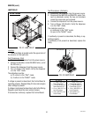
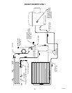
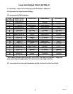
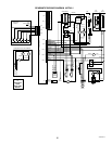
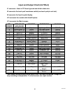
Input and Output Chart (ULTRA-1)
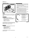
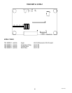
J9 connector for liquid crystal display.
J11 connector for touch pad/ membrane switch (see touch pad pin out test).
J10 connector for Main harness
PIN
NUMBER
WIRE COLOR
AND GAUGE
FUNCTION COMPONENT VOLTAGE
1
Rectifier
2
Output
Output
Output
Output
Torque Sensor
3
Temp Sensor
4
Torque Sensor
5
Rectifier
6
Not used
Not used
Not used
Not used
7
8
Auger Motor
9
Auger Motor
10
11
12
13
Output
14
Output
15
16
17
18
Not used
Not used
19
Output
Output
20
Supply
*With sensor disconnected you will read +5VDC, but when connected, voltage will
vary according to temperature. To check sensor, see repair section.
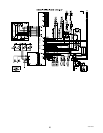
J1 connector - black is TIC board ground and white is data wire.
White/Blue 18
Blue 22
White/Gray 22
White/Black 18
Not used
Not used
Brown/White 18
Black 18
Yellow 22
Gray 22
Blue/Black 18
White/Black 22
Not used
White 18
Not used
Brown 22
Tan 22
Brown/Black 18
Violet 18
Orange 18
PC Board
Hot Gas Temp
Lamp Relay
Condenser Fans
Lamp Relay
Sensors
Not used
PC Board
Not used
Solenoid
Compressor Relay
Neutral
Not used
Not used
*
*
5VDC
5VDC
12VDC
120VAC
120VAC
120VAC
120VAC
120VAC
120VAC
+12VDC
5VDC
Not used
Not used
- - - - -
--
- - - - -
- - - - - -- - - - - -
Neutral
Output/Switched
Board Ground
Input/Signal
Input/Signal
41084 102709