


13
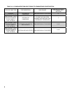
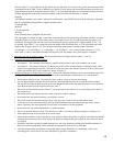
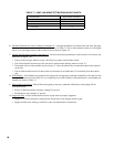
shown in Table 7.1 are in addition to the fi rst elbow on top of the boiler. For vertical vent systems, the maximum vertical
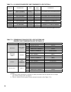
vent lengths shown in Table 7.8 are in addition to two elbows. If more elbows are desired, the maximum allowable vent
length must be reduced by the amount shown in Table 7.7 for each additional elbow used. Termination fi ttings are never
counted, although the length of the concentric terminal section, included with the boiler, is counted.
Example:
A 60/100mm concentric vent system is planned for a horizontally vented FCM120 which has the following components:
80/125 x 60/100mm Reducing Elbow (supplied with the boiler)
5 ft Straight Pipe.
90 elbow
1 ½ ft Straight Pipe
45 Elbow
Uncut Terminal Section (supplied with the boiler)
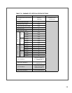
The Vent Option #1 column in Table 7.1 describes a horizontal direct vent system using 60/100mm concentric vent pipe.
From this column, we see that a FCM120 may have a vent length of up to 18 ft. The 90 degree reducing elbow is not
considered. The length of the terminal section (not including the plastic terminal itself) is approximately 22 1/2” (1.9
ft) installed. From Table 7.7, we see that the equivalent length of the 60/100mm elbow is 4.5 ft and that the equivalent
length of the 45 degree elbow is 4 ft. The total equivalent length of the planned venting system is therefore:
5 ft (Straight ) + 4.5 ft (90 Elbow) + 1.5 ft (Straight ) + 4 ft (45 Elbow) + 1.9 ft (Uncut Terminal Section) = 16.9 ft.
Since Table 7.1 shows a maximum allowable vent length of 18 ft, the planned vent system length is acceptable.
3) Minimum Vent and Air Intake Lengths - Observe the minimum vent lengths shown in tables 7.1 and 7.8.
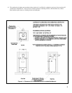
4) Permitted Terminals for Horizontal Venting:
• Vent Option 1 - The concentric vent terminal is supplied with the boiler as part of the standard vent system.
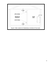
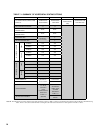
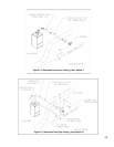
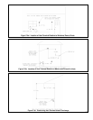
• Vent Option 2 - The exhaust terminal is U.S. Boiler part 8110701. The air intake fi tting is a 90 degree elbow with a
rodent screen supplied by the installer. This elbow is made out of the same material as the rest of the air inlet system
(either galvanized or PVC) and is installed as shown in Figure 7.3.
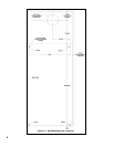
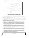
5) Horizontal Vent and Air Intake Terminal Location - Observe the following limitations on the vent terminal location (also
see Figure 7.6). When locating a concentric terminal, observe the limitations outlined below for “vent terminals”.
• Vent terminals must be at least 1 foot from any door, window, or gravity inlet into the building.
• For twin pipe terminals, maintain the correct clearance and orientation between the vent and air intake terminals.
The vent and air intake terminals must be at the same height and their center lines must be between 12 and 36 inches
apart. Both terminals must be located on the same wall.
• The bottom of all terminals must be at least 12” above the normal snow line. In no case should they be less than 12”
above grade level.
• The bottom of the vent terminal must be at least 7 feet above a public walkway.
• Do not install the vent terminal directly over windows or doors.
• The bottom of the vent terminal must be at least 3 feet above any forced air inlet located within 10 feet.
• A clearance of at least 4 feet horizontally must be maintained between the vent terminal and gas meters, electric
meters, regulators, and relief equipment. Do not install vent terminal over this equipment.
• Do not locate the vent terminal under decks or similar structures.
• Top of vent terminal must be at least 5 feet below eves, soffi ts, or overhangs. Maximum depth of overhang is 3 ft.
• Vent terminal must be at least 6 feet from an inside corner.
• Under certain conditions, water in the fl ue gas may condense, and possibly freeze, on objects around the vent terminal
including on the structure itself. If these objects are subject to damage by fl ue gas condensate, they should be moved
or protected.
• If possible, install the vent and air intake terminals on a wall away from the prevailing wind. Reliable operation of
this boiler cannot be guaranteed if these terminals are subjected to winds in excess of 40 mph.
• Air intake terminal must not terminate in areas that might contain combustion air contaminates, such as near
swimming pools. See Section IV for
more information on possible contaminates.