


53
XII Operation
1) The FCM boiler uses a microprocessor based control, known as a “MCBA”, to manage all boiler functions
including fl ame supervision and modulation. Two set point or “target” boiler supply temperatures are stored in the
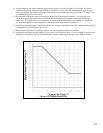
MCBA’s memory; one for space heating and one for domestic water production. If an outdoor temperature sensor
is connected to the boiler, the space heating supply set point will automatically adjust downwards as the outdoor
temperature increases. For more information on this feature see the discussion on boiler water reset below.
The MCBA modulates the boiler input by varying the fan speed. As the fan speed increases, so does the
amount of gas drawn into the blower. As a result, a fairly constant air-fuel ratio is maintained across all inputs.
The MCBA determines the input needed by looking at both current and recent differences between the supply
temperature and the set point temperature. As the supply temperature approaches the set point temperature, the fan will
slow down and the input drop. Depending on the model boiler, the minimum input is between ¼ and 1/5 of maximum
input.
The MCBA also monitors boiler return and fl ue temperatures. In addition, all other safety controls, including the low
water cut-off and safety limit, are connected into the MCBA. The MCBA uses input from all of these controls to either
shut down the boiler when an unsafe condition exists or, in some cases, to correct the problem.
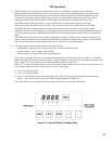
2) The display panel has three primary modes of operation. These are:
• Standby Mode – Displays boiler’s current status. This is the default operating mode.
• Parameter Mode – Used to change control settings
• Information Mode – Displays boiler operating temperatures
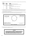
Under normal conditions, the boiler is in standby mode and the display looks like that shown in Figure 12.1. The three
digits to the right of the decimal point are the boiler’s supply temperature. The digit to the left of the decimal point is the
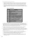
boiler’s status code. A list of status codes, and their meanings, is shown in Table 12.3.
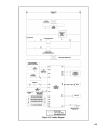
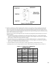
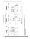
Figure 12.2 is a map of the menu structure for the control panel. Push the mode key to move from one mode to the next.
As you change modes, the mode you are entering is shown on the display:
a) “PArA” for Parameter Mode
b) “Info” for Information Mode
c) “Stby” for Standby Mode. Upon entering standby mode, “Stby” will briefl y appear on the display and then the
display will show the boiler’s status along with the supply temperature (Figure 12.1).
The control will return to standby mode from any other mode if no key is pressed for 20 minutes.
Figure 12.1: Normal Display In Standby Mode