


56
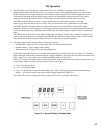
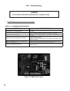
3) Two basic types of errors codes are shown on the display:
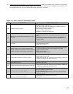
• Soft Lockout Codes – When a soft lockout occurs, the boiler will shut down and the display will alternate between
the number “9” and the letter “b” followed by a two digit service code. A list of these codes, and their meanings, is
shown in Table 14.3. The boiler will automatically restart once the condition that caused the lockout is corrected.
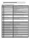
• Hard Lockout Codes – When a hard lockout occurs, the boiler will shut down and the display will fl ash the letter
“E” followed by a two digit service code. A list of these codes, and their meanings, is shown in Table 14.4. Once the
condition that caused the lockout is corrected, the boiler will need to be manually reset using the RESET button on
the display.
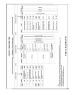
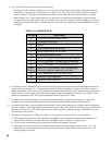
TABLE 12.3: BOILER STATUS
First Digit Boiler Status
0 Burner off - No call for heat or DHW
1 Pre-purge or post-purge
2 Ignition
3 Burner responding to call for heat
4 Burner responding to call for DHW
5 Checking air pressure switch
6 Burner off - Set point temperature has been reached
7 Call for heat ended. 10s heating post pump period
8 Call for DHW ended. 10s DHW post pump period
9 and b
Flashing
Burner off - on soft lockout. See Troubleshooting
Section to determine meaning of error code.
A Boiler responding to call from heating zone
H Burner on - Held in high fi re
L Burner on - Held in low fi re
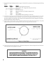
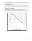
4) If an outdoor sensor is installed, the boiler will automatically adjust the heating zone set point temperature based on the
outdoor reset curve in Figure 12.4. The maximum set point is defi ned by parameter 4 (factory set to 180°F) when the
outdoor temperature is 0°F or below. The minimum set point temperature shown is 100°F when the outdoor temperature
is 60°F or above. As the outdoor temperature falls the supply water target temperature increases. For example, if the
outdoor air temperature is 30°F, the set point temperature for the supply water is 140°F.
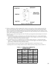
5) An indirect water heater thermostat can be connected between terminals 7 and 8 on the terminal strip. When this
thermostat closes, the central heating circulator will be turned off and the DHW circulator will be turned on.
6) An external limit control can be installed between terminals 3 and 4 on the terminal strip. Be sure to remove the jumper
between terminals 3 and 4 when adding an external limit control to the system. If the external limit opens, the boiler will
shut down and error code “b 26” will be displayed. If the limit installed is a manual reset type, it will need to be reset
before the boiler will operate.
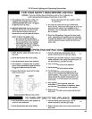
7) The sequence of operation for a FCM series boiler on a call for heat from a thermostat is as described below:
a) When power is fi rst turned on, 120V is provided to the MCBA, the combustion fan and the LWCO transformer. A
separate 50VA transformer, connected directly to the MCBA, powers all other low voltage circuits.
b) For the fi rst few seconds after power-up the control module goes through a self check.
c) When there is a call for heat, the control module checks to make sure the air pressure switch is open. If it is, the
combustion fan will be energized and will ramp up to ignition speed. When the air pressure switch closes, a 10
second prepurge is activated.