


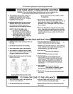

51
11) Perform a combustion test. Boilers equipped with a concentric vent system have a fl ue gas sample tap located in the
boiler vent collar (under the screw cap). For other vent systems, the sample probe may be inserted into the terminal.
If this is not possible, remove the fl ue temperature sensor and insert the analyzer probe in the sensor opening. For the
boiler to operate, this sensor will need to be remain connected to the wiring. If the fl ue gas sensor is removed, be sure to
replace it after combustion testing is complete.
Check CO
2
(or O
2
) and CO at both high and low fi re. The boiler may be temporarily locked into high or low fi re for 15
minutes as follows:
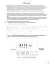
a) To lock the boiler in high fi re, simultaneously press and hold the “Mode” button and “+“ button until the display
fl ashes “H”, indicating that the boiler has been driven to high fi re. After this happens, allow the boiler to operate for
approximately 5 minutes before taking combustion readings.
b) To lock the boiler in low fi re, simultaneously press and hold the “Mode” button and “-“ button until the display
fl ashes “L”, indicating that the boiler has been driven to low fi re. After this happens, allow the boiler to operate for
approximately 5 minutes before taking combustion readings.
c) Normal modulation of the boiler should return 15 minutes after the boiler is locked in high or low fi re.
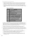
At both high and low fi re, CO readings should be less than 75 PPM. Typical CO
2
readings are shown in Table 11.3.
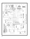
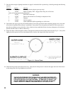
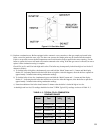
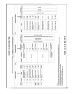
Figure 11.2: Gas Valve Detail
Model Fuel %CO
2
%O
2
FCM070
Natural Gas
9.4 4.4
FCM070
Propane
10.4 5.1
FCM090
Natural Gas
9.5 4.3
FCM090
Propane
10.5 5.0
FCM120 Natural Gas 9.5 4.3
FCM120 Propane 10.5 5.0
TABLE 11.3: TYPICAL CO
2
/O
2
COMBUSTION
READINGS RANGE