


4
III Before Installing
1) Safe, reliable operation of this boiler depends upon installation by a professional heating contractor in strict accordance
with this manual and the authority having jurisdiction.
• In the absence of an authority having jurisdiction, installation must be in accordance with this manual and
the National Fuel Gas Code, ANSI Z223.1.
• Where required by the authority having jurisdiction, this installation must conform to the Standard for
Controls and Safety Devices for Automatically Fired Boilers (ANSI/ASME CSD-1).
2) FCM boilers utilize aluminum heat exchangers constructed, tested, and stamped in accordance with ASME Boiler and
Pressure Vessel Code Case 2382-2. Some jurisdictions which require ASME boiler construction do not recognize this
Code Case and may not approve the installation of an aluminum boiler. Consult the authority having jurisdiction before
installing this boiler.
3) Read Section VII to verify that the maximum combustion air and exhaust pipe lengths will not be exceeded in the
planned installation. Also verify that the vent terminal can be located in accordance with Section VII.
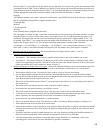
4) Make sure that the boiler is correctly sized:
• For heating systems employing convection radiation (baseboard or radiators), use an industry accepted sizing
method such as the I=B=R Heat Loss Calculation Guide (Pub. #H21 or #H22) published by the Hydronics Institute
in Berkely Heights, NJ.
• For new radiant heating systems, refer to the radiant tubing manufacturer’s boiler sizing guidelines.
• For systems including a Alliance™ indirect water heater, size the boiler to have either the DOE Heating Capacity
required for the Alliance™ or the net rating required for the heating system, whichever results in the larger boiler.
• For systems that incorporate other indirect water heaters, refer to the indirect water heater manufacturer’s
instructions for boiler output requirements.
5) Make sure that the boiler received is confi gured for the correct gas (natural or LP).
6) Make sure that the boiler is confi gured for use at the altitude at which it is to be installed.
NOTICE
This product must be installed by a licensed plumber or gas fi tter when installed
within the Commonwealth of Massachusetts. See Appendix A for additional
important information about installing this product within the Commonwealth of
Massachusetts.
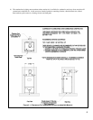
IV Locating the Boiler
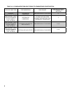
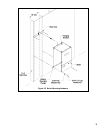
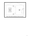
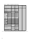
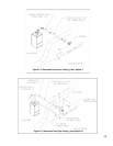
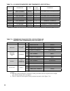
1) Observe the minimum clearances shown in Figure 4.1. These clearances apply to both combustible and non-
combustible materials. Observe the minimum clearances to combustibles for vent pipe shown in Table 4.2.
2) Note the recommended service clearances in Figure 4.1. These service clearances are recommended, but may reduced
to the combustible clearances provided:
a. Access to the front of the boiler is provided through a door
b. Access is provided to the condensate trap and transformer located underneath the boiler.
3) When the boiler is installed on the fl oor using the optional pedestal kit, the boiler may be installed on a non-carpeted
combustible surface.
4) The relief valve must be installed in the factory specifi ed location.
5) The boiler should be located so as to minimize the length of the vent system.