


18
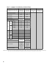
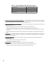
TABLE 7.7: VENT/ AIR INTAKE FITTING EQUIVALENT LENGTH
VENT FITTING EQUIVALENT LENGTH (ft)
60/100mm 90 CONCENTRIC ELBOW 4.5
60/100mm 45 CONCENTRIC ELBOW 4.0
3” 90 ELBOW 5.5
3” 45 ELBOW 4.0
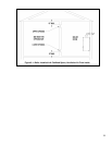
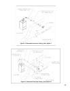
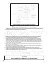
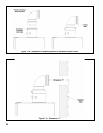
6) Permitted Terminals for Vertical Venting (Vent Option 5) - A straight termination is installed in the end of the vent pipe.
Vent manufacturer part numbers for these screens are shown in Table 7.5. The air inlet terminal consists of a 180 degree
elbow (or two 90 degree elbows) with a rodent screen as shown in Figure 7.9.
7) Vertical Vent Terminal Locations (Vent Option 5) - Observe the following limitations on the location of all vertical vent
terminals (see Figure 7.9):
• The top of the vent pipe must be at least 2 feet above any object located within 10 feet.
• The vertical distance between top of the vent and air inlet terminal openings must be at least 12”.
• The bottom of the air inlet terminal must be at least 12” above the normal snow accumulation that can be expected
on the roof.
• The air intake terminal must be located on the roof and must be no further than 24” horizontally from the exhaust
pipe.
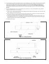
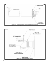
8) Wall thimbles – Wall thimbles are required where single wall vent pipe passes through combustible walls with less than
the required clearance shown in Table 4.2 or as required by local codes. Stainless vent manufacturer’s wall thimble part
numbers are shown in Table 7.5.
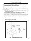
9) Pitch of Horizontal Piping - Pitch all horizontal piping so that any condensate which forms in the piping will run
towards the boiler:
• Pitch U.S. Boiler horizontal concentric venting 5/8” per foot
• Pitch Stainless steel venting 1/4” per foot.
10) Supporting Pipe - Vertical and horizontal sections of pipe must be properly supported:
• Support U.S. Boiler concentric venting near the female end of each straight section of pipe.
• Support stainless steel venting as called for by the vent manufacturer’s instructions.