


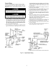
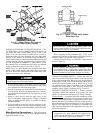
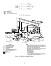
INSTALL WATER TO OIL COOLER ON FA COMPRE-
SORS — On FA compressors, water must be piped to the oil
cooler heat exchanger (located under the suction pipe to the
compressor). The water supply may be either city water or
chilled water. Pipe city water to an open sight drain. Chilled
water enters via the cooling entering water intake (Fig. 15).
City water must be clean and noncorrosive. Water side
erosion or corrosion of the oil cooler coil may lead to
extensive machine damage not covered by the standard
warranty.
If water from the machine chilled water circuit is used for
oil cooling, it should enter the oil cooler from the entering
water line of the machine cooler. Water leaving the oil cooler
should connect to the leaving water line of the machine cooler
at a point downstream from the chilled water sensor, so that
oil cooler leaving water temperature does not affect the sen-
sor readings.
Locate the oil cooler leaving water connection at some
distance from any water temperature indicators. On single-
pass machines, water leaving the oil cooler should be con-
nected into the suction side of the chilled water pump so that
adequate pressure drop is assured for oil cooling.
The nominal conditions for oil cooler water flow are:
Flow rate .......................30gpm(1.9 L/s)
Leaving temperature ........85to100F(29to38C)
Pressure drop at oil cooler .......7.25 psid (50 kPad)
Max differential pressure across closed
solenoid valve ..............150psid (1034 kPad)
The oil cooler connections are 1
1
⁄
4
in. FPT.
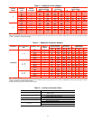
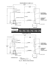
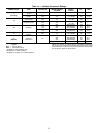
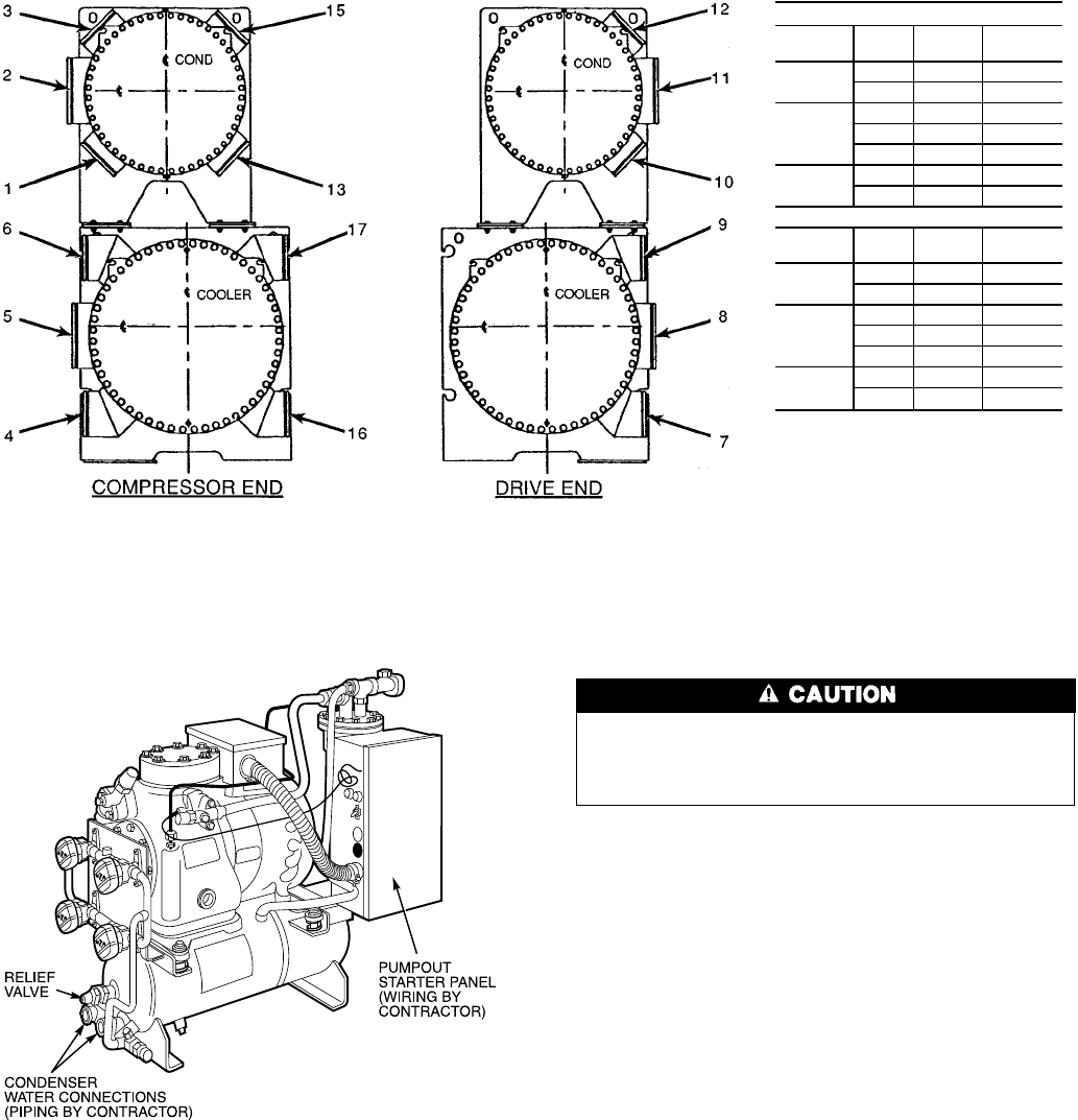
FRAME 4 MARINE WATERBOXES
COOLER WATERBOX
Pass In Out
Arr.
Code
1
85 A
58 B
2
79 C
46 D
16 17 G
3
76 E
49 F
CONDENSER WATERBOX
Pass In Out
Arr.
Code
1
11 2 P
211 Q
2
10 12 R
13 S
13 15 Y
3
10 3 T
112 U
NOTES:
1. The vents for these waterboxes are 1 in. FPT at the top of each box. The
drains are 1 in. FPT, at the bottom.
2. Victaulic connections are standard.
3. Flanged connections are optional.
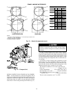
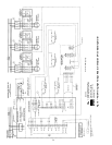
Fig. 13 — Nozzle Arrangements (cont)
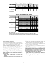
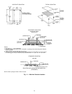
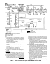
Fig. 14 — Pumpout Unit
19