


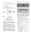
Insulate Motor Terminals and Lead Wire Ends — Insulate
compressor motor terminals, lead wire ends, and electrical
wires to prevent moisture condensation and electrical arc-
ing. For low-voltage units (up to 600 v), insulate the elec-
trical terminals as follows:
1. Insulate each terminal by wrapping with one layer of
insulation putty.
2. Overwrap putty with 4 layers of vinyl tape.
High-voltage units require special terminal preparation. The
vinyl tape is not acceptable; a high voltage tape must be used.
Installer is responsible for any damage caused by improper
wiring between starter and compressor motor.
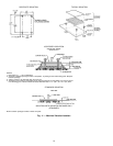
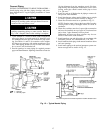
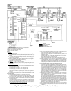
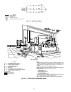
Connect Power Wires to Oil Pump Contactor — Connect power
wires to oil pump contactor mounted in machine power panel.
(See Fig. 19.) Use the electrical disconnect located in the
machine starter (if supplied), or a separate fused disconnect
as shown on job wiring diagrams. Check that power supply
voltage agrees with oil pump voltage. Follow correct phas-
ing for proper motor rotation.
Do not wire into the top surface of the power panel. Knock-
outs are provided on the underside of the panel.
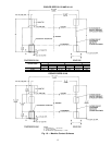
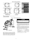
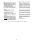
Connect Power Wires to Oil Heater Contactor — Connect
control power wiring between the oil heater contactor ter-
minals (Fig. 17 and 18) and terminals LL1 and LL2 on the
field wiring strip in the compressor motor starter. Refer to
Fig. 21 and wiring label on the chiller power panel.
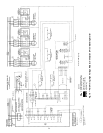
Voltage to terminals LL1 and LL2 comes from a con-
trol transformer in a starter built to Carrier specifica-
tions. Do not connect an outside source of control power
to the compressor motor starter (terminals LL1 and LL2).
An outside power source will produce dangerous volt-
age at the line side of the starter, because supplying volt-
age at the transformer secondary terminals produces in-
put level voltage at the transformer primary terminals.
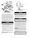
Connect Communication and Control Wiring from Starter to
Power Panel — Connect control wiring from main motor starter
to the chiller power panel.All control wiring must use shielded
cable. Also connect the communications cable. Make sure
the control circuit is grounded in accordance with applicable
electrical codes and instructions on chiller control wiring
label.
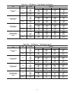
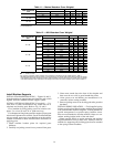
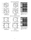
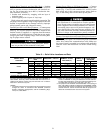
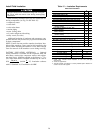
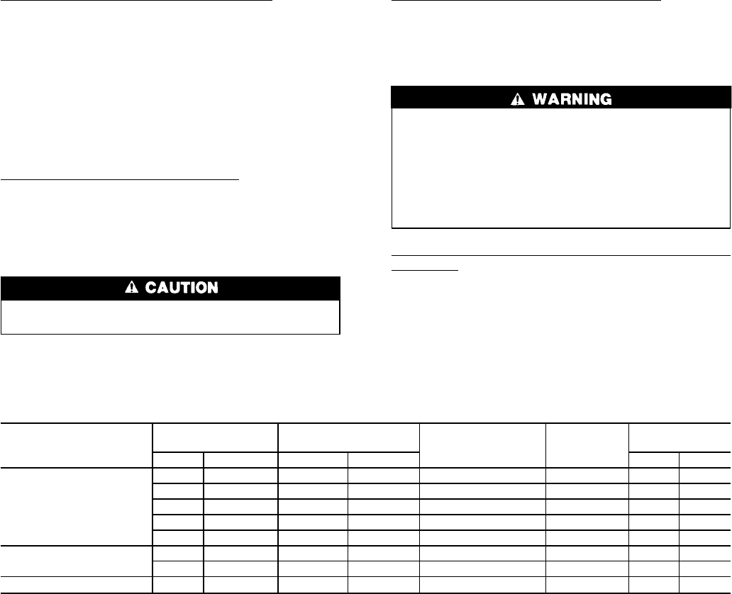
Table 13 — Relief Valve Locations and Data
RELIEF VALVE
LOCATION
HEAT EXCHANGER
SIZE
REQUIRED C FACTOR
NOMINAL OUTLET
PIPE SIZE (in.)
NUMBER OF
VALVES
RATED RELIEF
PRESSURE
Cooler Condenser lb air/min. kg air/sec. psig kPa
Cooler
31-33 31-33 139.7 1.06 1
1
⁄
4
FPT 2 225 1551
41-43 41-43 158.8 1.20 1
1
⁄
4
FPT 2 225 1551
44 51-53 164.6 1.24 1
1
⁄
4
FPT 2 225 1551
45-47 45-47 216.3 1.64 1
1
⁄
4
FPT 3 225 1551
48 55-57 228.5 1.73 1
1
⁄
4
NPT 3 225 1551
Economizer/Storage
Vessel
41-44 ALL 64.2 0.49 1
1
⁄
4
NPT 2* 225 1551
45-48 ALL 84.3 0.64 1
1
⁄
4
FPT 2* 225 1551
Pumpout Unit Condenser ALL ALL 1.5 0.01
3
⁄
8
in. Male Flare MPT 1 385 2655
*To ensure relief valve serviceability, and as required in ASHRAE 15,
latest edition, three-way valves and redundant relief valves are in-
stalled on the storage vessel. Only one half of the ‘‘No. of Valves’’
listed are in service at any time.
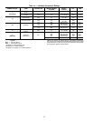
NOTES:
1. The cooler relief C-factor is for both cooler and condenser vented
through the cooler in accordance with ASHRAE (American
Society of Heating, Refrigeration, and Air Conditioning Engi-
neers) 15, latest edition.
2. Relief valve discharge pipe sizing is to be calculated per latest
version of ASHRAE 15, using the tabulated C-factors and nom-
inal pipe size listed above. Cooler and economizer/storage ves-
sel rated relief valve pressure is 225 psig (1551 kPa).
3. The pumpout unit condenser contains less than 110 lb (50 kg) of
HFC-134a, which is a GroupA1 refrigerant.TheASHRAE 15 stand-
ard exempts small-volume vessels from the requirement to vent
outside. However, Carrier recommends that the pumpout con-
denser be connected to the rest of the vent system.
21