


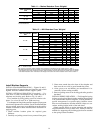
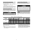
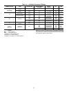
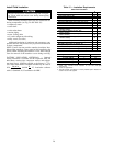

Table 14 — Individual Component Ratings
POWER SOURCE ITEM AVERAGE kW
DESIGN CENTER
VOLTAGE
SUPPLY
V-PH-HZ
FLA LRA
1*
(17EX Only)
Seal Leakage
Pump
0.23 115 115-1-50/60 4.78 21.7
Motor Space
Heater
0.50 115 115-1-50/60 4.35 4.35
1†
Control Module
and Actuator
0.40 115
115-1-60
3.50 —
115-1-50
Oil Sump Heater 1.00 115
115-1-60
8.70 —
115-1-50
2† Oil Pump
1.35 220 200/240-3-60 4.32 24.5
1.30 430 380/480-3-60 2.15 12.2
1.37 563 507/619-3-60 2.13 25.0
1.49 230 220/240-3-50 4.83 28.0
1.49 393 346/440-3-50 2.59 12.2
1**
Hot Gas
Bypass
0.20 115 115-1-50/60 2.00 4.75
3**
(Optional)
Pumpout
Compressor
3.41
204 200/208-3-60 10.90 63.5
230 220/240-3-60 9.50 57.5
460 440/480-3-60 4.70 28.8
575 550/600-3-60 3.80 23.0
400 380/415-3-50 4.70 28.8
LEGEND
FLA — Full Load Amps
LRA — Locked Rotor Amps
*Available for 17EX machines only.
†Available for 17/19EX machines.
**Available as an option on 17/19EX machines.
NOTE: The oil pump is powered through a field wiring terminal into
the power panel. Power to the controls and oil heater via the power
panel must be on circuits that can provide continuous service when
the compressor starter is disconnected.
22