


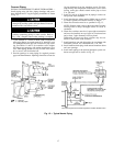
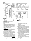
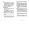
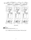
LEGEND
Factory Wiring
Field Wiring
Oil Pump Terminal
Power Panel Component Terminal
Fig. 19 — Oil Pump Wiring
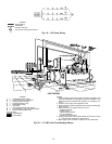
19EX SHOWN
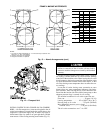
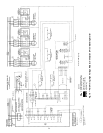
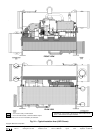
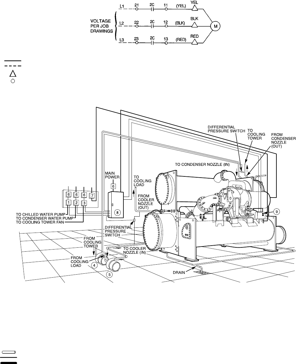
LEGEND
1—Chilled Water Pump Starter
2—Condenser Water Pump Starter
3—Cooling Tower Fan Starter
4—Condenser Water Pump
5—Chilled Water Pump
6—Disconnect
7—Oil Pump Disconnect (See Note 5)
8—Free-Standing Compressor Motor Starter
9—Chiller Auxiliary Power Panel
Piping
Control Wiring
Power Wiring
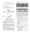
NOTES:
1. Wiring and piping shown are for general point-of-connection only
and are notintended to show details for a specific installation.Cer-
tified field wiring and dimensional diagrams are available on re-
quest.
2. All wiring must comply with applicable codes.
3. Refer to Carrier System Design Manual for details regarding pip-
ing techniques.
4. Wiring not shown for optional devices such as:
• Remote Start-Stop
• Remote Alarms
• Optional Safety Device
• 4 to 20 mA Resets
• Optional Remote Sensors
5. Oil pump disconnect may be located within the enclosure of Item
8 — Free-Standing Compressor Motor Starter.
6. Water piping to the oil cooler is required on FA compressors.
Fig. 20 — 17/19EX with Free-Standing Starter
26