


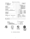
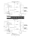
NOTES:
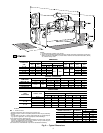
1. Certified drawings available upon request.
2. Serviceaccess should beprovided perAmerican Society of Heating,Refrigeration, andAir Con-
ditioning Engineers (ASHRAE) 15, latest edition, National Fire Protection Association (NFPA)
70, and local safety codes.
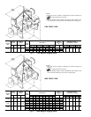
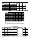
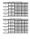
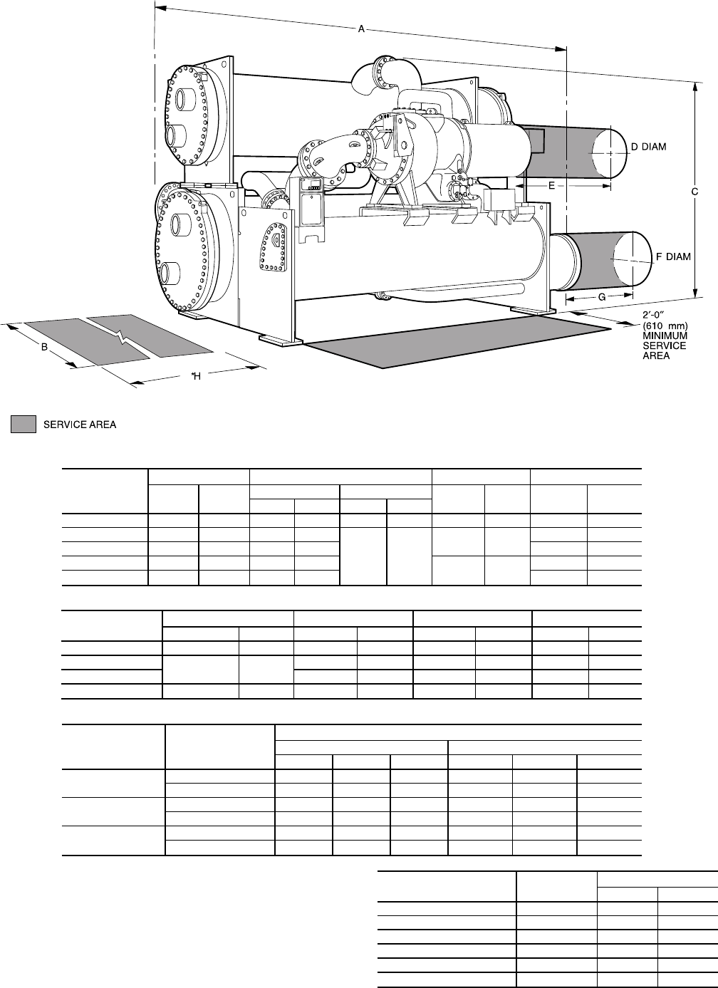
DIMENSIONS
CONDENSER
SIZE
A (LENGTH)† B (WIDTH) C (HEIGHT) H (TUBE PULL)
ft-in. mm
17EX** 19EX
ft-in. mm ft-in. mm
ft-in. mm ft-in. mm
31-33 15-6 4724 N/A N/A 8-10 2692 10-8
1
⁄
2
3264 12-10 3912
41-43 15-6 4724 N/A N/A
9-4
1
⁄
2
2858
12-2 3708
12-10 3912
45-47 20-3 6172 12-2 3708 17- 6 5334
51-53 15-6 4724 N/A N/A
12-5 3785
12-10 3912
55-57 20-3 6172 12-2 3708 17- 6 5334
SERVICE CLEARANCES
COMPONENT
D (DIAMETER)†† E (LENGTH)†† F (DIAMETER) G (LENGTH)
ft-in. mm ft-in. mm ft-in. mm ft-in. mm
Motor DB - DQ 1-11
1
⁄
4
591 3- 7
1
⁄
2
1105 — — — —
Motor EA - ED
2- 2
3
⁄
4
679
3-10
1
⁄
4
1175 — — — —
Motor EE 4- 1
1
⁄
4
1251 — — — —
Low-Side Float — — — — 2-6
1
⁄
2
775 1-0 305
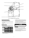
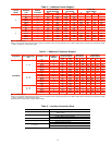
NOZZLE SIZES
HEAT
EXCHANGER
NOZZLE TYPE
NOZZLE SIZES (in.)ሻ
Cooler Passes Condenser Passes
123 1 2 3
31-33
Marine 12 10 10 12 10 10
NIH 12 10 10 — 10 10
41-48
Marine 20 14 12 20 14 12
NIH 18 14 10 18 12 10
51-57
Marine — — — — 16 —
NIH — — — 20 16 —
LEGEND
NIH — Nozzle-In-Head
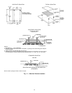
*Distance required for tube removal may be either end.
†Based on 2-pass, nozzle-in-head (NIH) waterboxes with 150 psi (1038 kPa)
covers.
**Overall width of units with 17 Series compressors will vary greatly depend-
ing upon the application. See the appropriate certified drawings.
††For hermetic motors (19 Series) only.
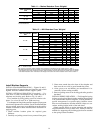
The table at right provides additional information on nozzle sizes. Victaulic
grooves are standard for these nozzles. Optional 150 psi (1034 kPa) and
300 psi (2068 kPa) flanges are available.
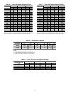
¶In conformance with ASA B36.10 (American Standards Association).
NOMINAL PIPE SIZE (in.) SCHEDULE¶
WALL THICKNESS
in. mm
10 40 .365 9.27
12 Std .375 9.53
14 30 .375 9.53
16 30 .375 9.53
18 Std .375 9.53
20 20 .375 9.53
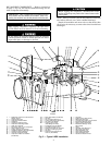
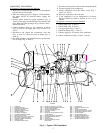
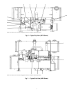
Fig.9—Typical Dimensions
9