


Install Field Insulation
Protect insulation from weld heat damage and weld splat-
ter. Cover with wet canvas cover during water piping
installation.
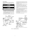
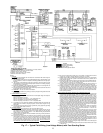
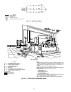
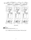
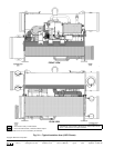
When installing insulation at the job site, insulate the fol-
lowing components (see Fig. 24 and Table 15):
• compressor motor
• cooler shell
• cooler tube sheets
• suction piping
• motor cooling drain
• oil cooler refrigerant side tubing
• utility vessel (low side)
Additional insulation of condenser and compressor com-
ponents and lines may be necessary to prevent condensation
on these components.
NOTE: Carrier does not provide waterbox insulation. Insu-
lation of the waterbox covers must be field supplied at the
jobsite. When insulating the waterbox covers, allow enough
room for removal of the waterbox covers during servicing.
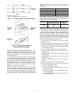
FACTORY INSULATION (OPTIONAL) — Optional
factory insulation is available for the evaporator shell and
tube sheets, suction pipe, compressor motors, and refriger-
ant drain line(s). Insulation applied at the factory is
3
⁄
4
in.
(19.0 mm) thick and has a thermal conductivity K value of
Btu
● in. W
0.28 (0.0404 °C). Insulation conforms
hr
● ft
2
● °F
m
with UL Standard 94, Classification 94 HBF.
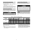
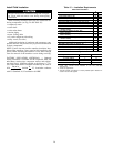
Table 15 — Insulation Requirements
Sheet Foam Insulation
COMPONENT
ft
2
m
2
Cooler Shell (Sizes 31-33) 254 23.6
Cooler Shell (Sizes 41-44) 306 28.4
Cooler Shell (Sizes 45-48) 374 34.7
Economizer Low Side Float Chamber 48 4.5
Economizer Main Shell (with cooler sizes 31-44) 85 7.9
Economizer Main Shell (with cooler sizes 45-48) 115 10.1
Suction Line 25 2.3
Cooler Marine Waterbox (1 or 3 pass, with
frame-3 coolers)
126 11.7
Cooler Marine Waterbox (2 pass, with
frame-3 coolers)
100 9.3
Cooler Marine Waterbox (1 or 3 pass, with
frame-4 coolers)
158 14.7
Cooler Marine Waterbox (2 pass, with
frame-4 coolers)
123 11.4
Cooler NIH Waterbox (with frame-3 coolers) 74 6.9
Cooler NIH Waterbox (with frame-4 coolers) 88 8.2
Main Motor Shell (with −51 through −89
compressors)
27 2.5
Main Motor Shell (with 421 through 469 compressors) 27 2.5
Main Motor Shell (with 531 through 599 compressors) 41 3.8
Foam Tubing Insulation
TYPE Ft m
1
1
⁄
8
؆ Foam Tubing 9 2.7
1
5
⁄
8
؆ Foam Tubing 2 0.6
2؆ Foam Tubing 9 2.7
5؆ Foam Tubing 14 4.3
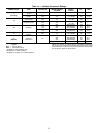
NOTES:
1. Cooler value includes marine waterbox on one end (even-pass
arrangement).
2. Values are approximate.
3. Thermal insulation is available as a factory-installed option. Waterbox in-
sulation must be field supplied.
28