


CLEVELAND RANGE OGB 20.20
SEQUENCE OF OPERATIONS
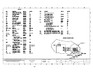
When using these instructions refer to the OGB 6.20 wiring schematic.
1 When 120 VAC is applied to the combi, it is sent to the Power Control Switch (S1).
2 When the Power Control Switch (S1) is closed
a The red light in the switch is energized.
b 120 VAC is sent through the line filter (Z1) then through the 20 amp fuse (F10.1)
to terminal L1 on the Motor Drive (U10.1)
c 120 VAC is sent through the line filter (Z2) then through the 20 amp fuse (F10.2)
to terminal L1 on the Motor Drive (U10.2)
d 120vac is sent through the 2 amp fuse (F1.1) to
• To terminals 1 and 2 of connector X1 on the Upper Hot Air Power Burner
Control (U20)
• To terminals 1 and 2 of connector X1 on the Steam Power Burner Control
(U21)
• To terminals 1 and 2 of connector X1 on the Lower Hot Air Power Burner
Control (U22)
• The 12 VDC Power Supply (G1)
◊ 12 VDC is sent to terminals 1 and 2 of connector X28 on the Gas Board
(A20)
◊ 12 VDC is sent to terminal 3 and 4 of connector X10 on the Control Board
(A10)
• To terminal 1 of connector X12 on the Control Board (A10)
e With 12 VAC to the Control Board (A10) The Operation Board (A11) is
energized
• An alarm will sound for one second
• All the LED’s and the display will energize one at a time.
• “STARTING” will be displayed for 3 seconds
• “Please wait” will be displayed
• The international model number will be displayed
• The time and date will be displayed and this will continue until the on/off
switch is depressed.
3 When the ON/OFF is depressed with the combi in the steam mode
a After a date change (the first time the combi is turned on) the display will ask
“Generator Flush?”. If no answer is given in 10 seconds or a yes is indicated the
flush will begin.
• 120 VAC is sent from terminal 1 of connector X13 on the Control Board
(A10) to the Generator Pump (M4).
• As the water level drops below the probes the fill solenoid (Y3) will energize.
This rocking of the water will help flush scale from the generator.