


◊ In the full mode (3 drops in the display) the Y2 valve will be energized
continuously.
f When the timer counts to 0 or the core temp probe (B10) reaches the set amount
the cycle .
6 With the combi in the Combi mode with time on the timer, the door closed and the
start switch is depressed
a The front display will include a lighted bar under the Combi symbol
• When the heat circuit is energized the heat symbol will be energized
• The cooking mode symbol will be energized.
• The time display will invert and begin to count down.
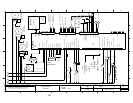
b The fan circuit is energized by the Control Board (A10) transmitting and
receiving a signal from terminals 5,6, and 7 on connector X10 to connector X12
on the Motor Drive Board (U10).
• The motor Drive Board sends a signal through the thermal switch in the motor
from Terminal 5 and receives on terminal 6
• If the thermal switch is not open the Motor Drive Board (U10) sends 240
VAC 3 phase to the motor.
• The motor reverses direction every 120 seconds with a 15 second coast.
c Hot air heat circuit is energized
• A signal is sent from terminal 8 of connector X15 on the Control Board (A10)
to terminal 4 of connector X2 on the Hot Air Power Burner and Fan Control
(U20) selecting the set speed of the combustion blower.
◊ When this speed is attained the signal is sent from terminal 2 of connector
X2 on the Hot Air Power Burner and Fan Control (U20) to terminal 2 of
connector X15 on the Control Board (A10)
• A request for heat is sent from terminal 3 of connector X12 on the Control
Board (A10) to terminal 10 on connector X1 on the Hot Air Control Module
(N20)
◊ 24 VAC is sent from terminal 2 of connector X2 on the Hot Air Control
Module (N20) to the hot surface igniter (R20).
◊ The gas valve is energized allowing gas and air into the burner chamber to
be ignited by the hot surface igniter.
◊ The Hot Air Burner Control Module (N20) senses at least 1.5 micro amps
DC from the flame sensor (P1) at terminal 3 of connector X2 and sends a
signal from terminal 2 of connector X1 to terminal 12 of connector X15
on the Control Board (A10)
• The heat circuit will remain energized until the cabinet set temperature is
reached as sensed at probe B6.
d The steam circuit is energized.
• 120 VAC is sent from terminal 4 of connector X12 on the Control Board
(A10) to the coil of the Y3 solenoid allowing water to be thrown against the
element until the bypass probe (B5) senses 183 degrees F.
• The heat circuit will remain energized until the cabinet set temperature is
reached