


5 With the combi in the Hot Air mode with time on the timer, the door closed and the
start switch is depressed
a The front display will include a lighted bar under the Hot Air symbol
• When the heat circuit is energized the heat symbol will be energized
• The cooking mode symbol will be energized.
• The time display will invert and begin to count down.
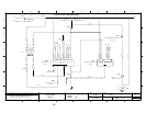
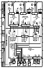
b The fan circuit is energized by the Control Board (A10) transmitting and
receiving a signal from terminals 5,6, and 7 on connector X10 to connector X12
on the Motor Drive Board (U10).
• The motor Drive Board sends a signal through the thermal switch in the motor
from Terminal 5 and receives on terminal 6
• If the thermal switch is not open the Motor Drive Board (U10) sends 240
VAC 3 phase to the motor.
• The motor reverses direction every 120 seconds with a 15 second coast.
• NOTE: If the set temperature is less than 212 degrees F than fan will be
pulsed on for 2 seconds every 60 seconds after the cabinet set temp (B6).
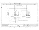
c Hot air heat circuit is energized
• A signal is sent from terminal 8 of connector X15 on the Control Board (A10)
to terminal 4 of connector X2 on the Hot Air Power Burner and Fan Control
(U20) selecting the set speed of the combustion blower.
◊ When this speed is attained the signal is sent from terminal 2 of connector
X2 on the Hot Air Power Burner and Fan Control (U20) to terminal 2 of
connector X15 on the Control Board (A10)
• A request for heat is sent from terminal 3 of connector X12 on the Control
Board (A10) to terminal 10 on connector X1 on the Hot Air Control Module
(N20)
◊ 24 VAC is sent from terminal 2 of connector X2 on the Hot Air Control
Module (N20) to the hot surface igniter (R20).
◊ The gas valve is energized allowing gas and air into the burner chamber to
be ignited by the hot surface igniter.
◊ The Hot Air Burner Control Module (N20) senses at least 1.5 micro amps
DC from the flame sensor (P1) at terminal 3 of connector X2 and sends a
signal from terminal 2 of connector X1 to terminal 12 of connector X15
on the Control Board (A10)
• The heat circuit will remain energized until the cabinet set temperature is
reached as sensed at probe B6.
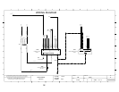
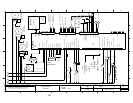
d When the condensate box is heated to 140 degrees F at the B3probe, 120 VAC is
sent from terminal 5 of connector X12 to the condenser valve (Y1) until the
temperature drops.
e
If the “Crisp and Tasty” mode is selected
• 120 VAC is sent from terminal 6 of connector X12 on the Control Board
(A10) to the Dehumidification Valve (Y2) to pull the humidity out of the
cabinet down the drain.
◊ In the light and medium modes (one and two drops in the display) the Y2
valve will be energized until the bypass probe (B5) is satisfied.