


INSTALLATION INSTRUCTIONS
7
PREPARING FOR THE INSTALLATION:
Be sure to read page 6 for the proper ventilation requirements before you begin.
When making your CUTOUT refer to page 8-9 for cabinet preparation.
Step 1: Unpack the unit, the regulator, and remove all packing between all the burners, rings,
and caps. Remove the grates from their boxes.
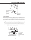
Step 2: With the necessary tools and hardware ready, measure the distance from the back and
sides of the countertop and cabinet to locate the position of the cooktop Cutout.
Step 3: Make your Cutout according to the dimensions given on page 8 & 9. Square the cutout
to the countertop.
Step 4: Lower the cooktop into the countertop cutout, being careful not to damage the
counter, inlet pipe threads, or the power cord of the cooktop.
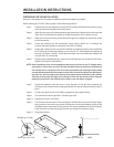
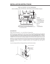
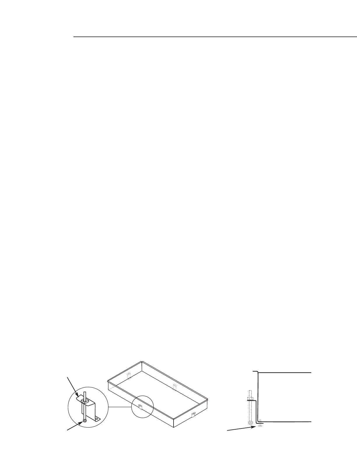
Step 5: Square the cooktop to the cutout and install the (4) retaining brackets onto the 8 holes
for CT-365 and (2) retaining brackets onto 4 holes for CT-304 located at the bottom of
the unit (See Figure 1 below). If hold down brackets are not installed, the cooktop will
not pull down to countertop.
Step 6: Tighten the 4 preloaded thumb screws which will keep the unit secured. Do Not Over-
tighten (See Figure 2 detail below).
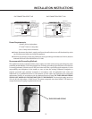
NOTE: Some installations may not have adequate clearance at the front for the ‘Z’-shaped retain-
ing bracket. In those cases, use the ‘L’-bracket provided.Fasten the bracket to the bottom of
the cooktop chassis using one of the screw holes provided for the retaining brackets. Make
sure the bracket extends out far enough to contact the inside of the cabinet face.While push-
ing down on the front edge of the cooktop from above,attach the bracket to the cabinet.
This step wil insure that the edge of the cooktop is flush with the counter surface. Plug the
adjacent unused hole in the cooktop chassis with a screw. See Figure 3, page 8.
Step 7: Install the regulator with the arrow in the direction of the gas flow (towards the
cooktop) using a sealant on the male pipe threads. Put burner rings and burner caps in
place.
Step 8: Connect the gas line to the unit. Refer to page 9 for gas supply hookup.
Step 9: Turn ball valve to let the gas flow. Check for gas leak.
Step 10: Plug the unit into a wall outlet.
Step 11: Turn the front burner knob on first and apply a match to the burner until the gas lights,
being cautious not to burn your hand or other parts of your body. When the gas is first
activated, there is air present in the gas lines.The match applied to the burner makes it
easier and safer to clear the air/gas mixture.Use Caution to avoid burn injury.
Step 12: Put grates in place.
FIG.1
FIG.2
Bracket (p/n 91164)
Screw (p/n 15117-02)
Screw (p/n 15001-22)