


C141-E124-01EN 3 - 127
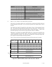
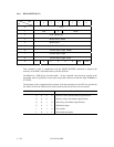
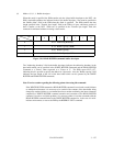
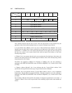
(4) Mode = 0, 0, 1, 1: Buffer descriptor
When this mode is specified, the IDD transfers only the 4-byte buffer descriptor to the INIT. the
IDD’s data buffer attributes are indicated in the 4-byte buffer descriptor. Zero must be specified in
the “Buffer offset” field in the CDB when this mode is specified. The IDD transfers the data
length specified in the “Transfer byte length” field in the CDB or 4 bytes, whichever portion of
data is smaller, to the INIT. When zero is specified in the “Transfer byte length” field, this
command is terminated without executing a data transfer.
Bit
Byte
76543210
0 X’02’ Addressing Boundary
1 X’78’ Buffer Capacity (MSB)
2 X’00’ Buffer Capacity
3 X’00’ Buffer Capacity (LSB)
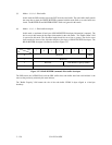
Figure 3.26 READ BUFFER command: buffer descriptor
The "Addressing boundary" field in the buffer descriptor indicates the addressing boundary in the
data buffer which can be specified in the WRITE BUFFER Command and the READ BUFFER
Command as a "Power" when expressed as a "Power of 2." The IDDs report X'02' (=2
2
),
indicating that it is possible to specify the address in 4-byte units. Also, the "Buffer capacity" field
indicates the byte length of the size of the data buffer which can be operated by the WRITE
BUFFER and READ BUFFER commands.
Note: Exercise caution regarding the following points when using this command.
If the WRITE BUFFER command or READ BUFFER command is used under a multi-initiator
or multitask environment, it is necessary to be careful of the contents of the data buffer being
changed by another initiator or a command that issues another task during the interval between
completion of WRITE BUFFER command execution and execution of the READ BUFFER
command. In order to avoid this problem, it is necessary either to issue the commands with the
READ BUFFER command linked to the WRITE BUFFER command or, in the case of a multi-
initiator environment, to reserve the IDD by the RESERVE UNIT command.