


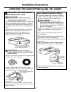
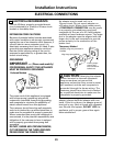
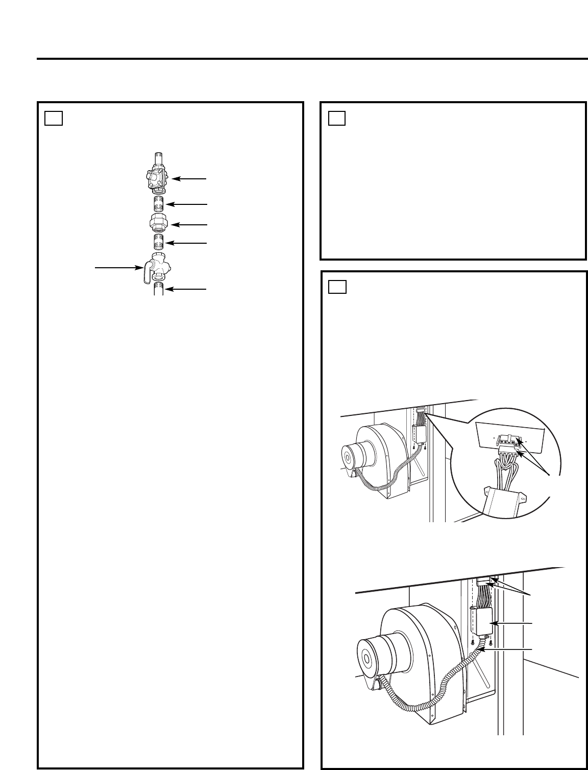
BLOWER ELECTRICAL
CONNECTIONS
• Loosen the two screws and remove and discard the
sheet metal connector cover on the cooktop bottom.
Save the screws for reinstallation later.
• Connect the 5-pin plug on the blower assembly to
the matching 5-pin receptacle on the bottom of the
cooktop.
• Fold all wires into the electrical enclosure. Secure
the enclosure with the screws removed earlier,
making sure that no wires are trapped.
• Plug the cooktop cord set into a suitable electrical
outlet. See step 17.
16
Installation Instructions
INSTALLING THE COOKTOP
INSTALL THE PRESSURE
REGULATOR
• Install the supplied pressure regulator in the gas line
as close to the cooktop inlet as possible. Allowances
for ventilation ducting may be necessary.
Make sure the regulator is installed in the right
direction.
• Install a manual shut-off valve in the gas line in an
easily accessible location.
NOTE: Instead of using solid piping to connect to
pressure regulator, an approved flexible metal
appliance connector may be used between the
shut-off valve and the pressure regulator, if local
codes permit.
Appropriate flare nuts and adapters are required at
each end of the flexible connector.
TEST FOR LEAKS
WARNING: DO NOT USE A FLAME TO CHECK
FOR GAS LEAKS! Do not use the cooktop until all
connections have been leak tested.
Perform leak test per the following instructions:
1. Purchase a liquid leak detector or prepare a soap
solution of one part water, one part liquid detergent.
2. When all connections have been made, make sure
all cooktop controls are turned to OFF and turn the
gas supply valve to ON.
3. Apply the liquid leak detector or the soap solution
around all connections from the shut-off valve to the
cooktop.
4. A leak is identified by a flow of bubbles from the
area of the leak.
5. If a leak is detected, turn the gas supply off. Tighten
the fitting. Turn the gas on and test again.
If the leak persists, turn the gas supply off and
contact your dealer for assistance. Do not attempt to
operate the cooktop if a leak is present.
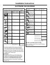
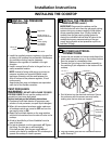
Regulator
Solid piping or
flexible connector
Union
Pipe stub
Shut-off
valve
15
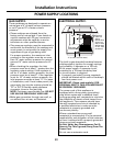
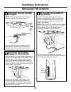
Solid piping
or flexible
connector
5-pin
connectors
Electrical
enclosure
Flexible
conduit
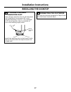
INSTALL THE PRESSURE
REGULATOR (cont.)
IMPORTANT: Disconnect the cooktop and the
individual shut-off valve from the gas supply piping
system during any pressure testing of that system
at test pressures greater than 1/2 psig. Isolate the
cooktop from the gas supply piping system by
closing the individual manual shut-off valve to the
cooktop during any pressure testing of the gas
supply piping system at test pressures equal to or
less than 1/2 psig.
15
5-pin
connectors
28