


18
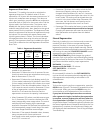
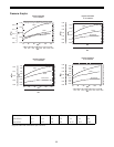
Water Usage Pattern
The other reserve option allows the control to adjust the
reserve based upon the historical water usage pattern of
the system. The control keeps track of the water usage for
each day of the week and uses that day’s average usage
multiplied by 1.2 as the reserve for that day. Every day at
the Time of Regeneration, the control recalculates the
day’s average water usage. If less than 10% of a day’s
average water usage is used, the control will not change
the day’s average. If more than twice the day’s average is
used, the control uses the actual usage in the reserve
calculation.
Since a new installation has no history of water usage, the
control multiplies the percent of capacity value set in
parameter P16 by the total system capacity to determine
starting average for each day of the week. The factory set
default value for P16 is 30 which means that 30% of the
total system capacity is used for the starting average for
each day.
Program parameter P15 is also used to select whether the
control waits until the Time of Regeneration set in
parameter P2 to start a regeneration, or if the control
should begin a regeneration immediately when the
capacity remaining is less than the reserve.
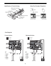
Removing the Valve Assembly for Servicing
1. Unplug the power cord.
2. Shut off water supply or put bypass valve(s) into
bypass position.
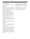
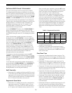
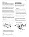
3. Remove cover and with screwdriver, relieve tank
pressure by pushing open valve No. 7 (rear flapper) on
control as shown (Figure 9).
Figure 9
4. When used with a globe valve bypass, loosen and
detach the inlet, outlet, regenerant and drain lines
from the valve. If using the 1265 bypass, loosen and
remove valve from bypass as well as loosening and
removing the regenerant and drain lines.
5. Unscrew (counterclockwise) and remove valve from
tank.
6. To replace the control valve, reverse the above
procedure.
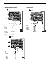
Preventive Maintenance
Injector Screen and Injector
Inspect and clean regenerant tank and screen filter on end
of regenerant pickup tube once a year or when sediment
appears in the bottom of the regenerant tank.
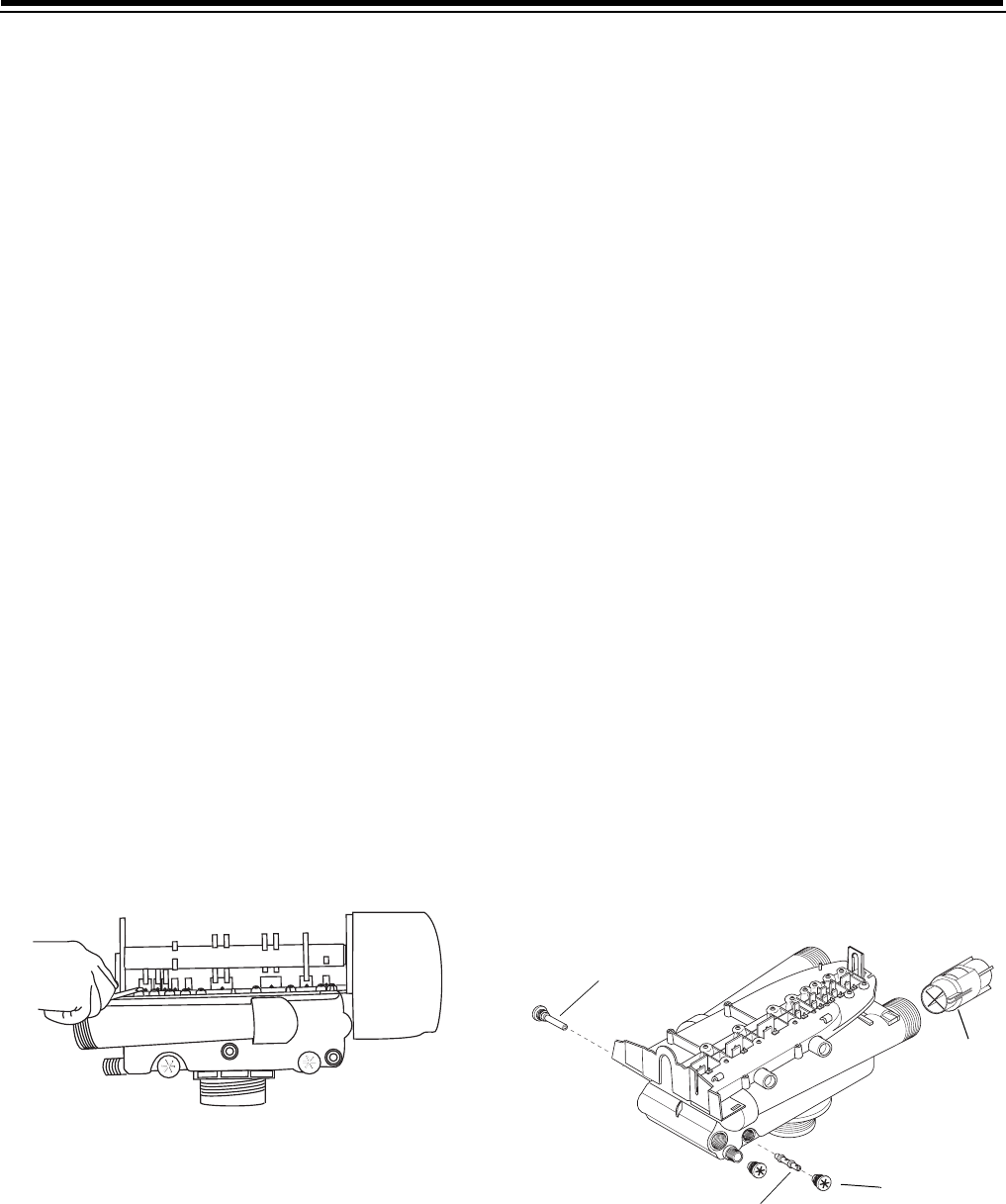
Clean injector screen and injector once a year:
1. Unplug the wall-mount transformer.
2. Shut off water supply or put bypass valve(s) into
bypass position.
3. Relieve system pressure by opening valve No. 7
(at rear) with a screwdriver (Figure 9).
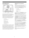
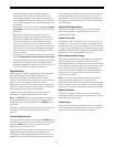
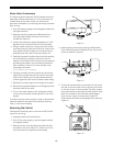
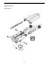
4. Using a screwdriver, remove injector screen and
injector cap (Figure 10).
5. Clean screen using a fine brush. Flush until clean.
6. Using a needle-nose pliers, pull injector straight out.
7. Flush water into the injector screen recess of the valve
body to flush debris out through the injector recess.
8. Clean and flush the injector.
9. Lubricate the O-rings on the injector, injector cap and
injector screen with silicone lubricant only!
10. Reinstall the injector, injector cap and injector screen.
IMPORTANT: Do not overtighten the plastic cap. Seat the
cap lightly into position. Overtightening may cause
breakage of the plastic cap that may not be immediately
evident.
11. Plug the wall-mount transformer into outlet; reset
clock if necessary.
12. Slowly open water supply valve or return bypass
valve(s) to the “service” position.
Figure 10
Injector
Injector Screen
Cap
Turbine