


3
Installation
All plumbing and electrical connections must conform to
local codes.
Inspect unit carefully for carrier shortage or shipping
damage.
Location Selection
1. The distance between the unit and a drain should be as
short as possible.
2. If it is likely that supplementary water treatment
equipment will be required, make certain adequate
additional space is available.
3. Since salt must be added periodically to the
regenerant tank, the location should be easily
accessible.
4. Do not install any unit closer to a water heater than a
total run of 10 feet (3 m) of piping between the outlet
of the conditioner and the inlet to the heater. Water
heaters can sometimes overheat to the extent they
will transmit heat back along the cold pipe into the
unit control valve.
Hot water can severely damage the conditioner. A
10-foot (3-m) total pipe run, including bends, elbows,
etc., is a reasonable distance to help prevent this
possibility. A positive way to prevent hot water
flowing from heat source to the conditioner, in the
event of a reverse flow situation, is to install a check
valve in the soft water piping from the conditioner. If a
check valve is installed, make certain the water
heating unit is equipped with a properly rated
temperature and pressure safety relief valve. Also,
be certain that local codes are not violated.
5. Do not locate unit where it or its connections
(including the drain and overflow lines) will ever be
subjected to room temperatures under 34
o
F (1
o
C) or
over 120
o
F (49
o
C).
6. Do not install unit near acid or acid fumes.
7. The use of resin cleaners in an unvented area is not
recommended.
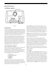
Water Line Connection
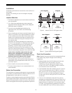
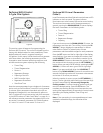
The installation of a bypass valve system is recommended
to provide for occasions when the water conditioner must
be bypassed for hard water or for servicing.
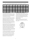
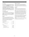
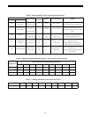
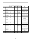
The most common bypass systems are the Autotrol Series
1265 bypass valve (Figure 1) and plumbed-in globe valves
(Figure 2). Though both are similar in function, the Autotrol
Series 1265 bypass offers simplicity and ease of operation.
Figure 1 - Autotrol Series 1265 Bypass Valve
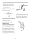
Figure 2 - Typical Globe Valve Bypass System
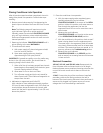
Drain Line Connection
Note: Standard commercial practices are expressed here.
Local codes may require changes to the following
suggestions.
1. Ideally located, the unit will be above and not more
than 20 feet (6.1 m) from the drain. For such
installations, using an appropriate adapter fitting,
connect 1/2-inch (1.3-cm) plastic tubing to the drain
line connection of the control valve.
2. If the backwash flow rate exceeds 5 gpm (22.7 Lpm) or
if the unit is located more than 20 feet (6.1 m) from
drain, use 3/4-inch (1.9-cm) tubing for runs up to 40
feet (12.2 m). Also, purchase appropriate fitting to
connect the 3/4-inch tubing to the 3/4-inch NPT drain
connection.
3. If the unit is located where the drain line must be
elevated, you may elevate the line up to 6 feet (1.8 m)
providing the run does not exceed 15 feet (4.6 m) and
water pressure at conditioner is not less than 40 psi
(2.76 bar). You may elevate an additional 2 feet (61 cm)
for each additional 10 psi (0.69 bar) water pressure.
Not in Bypass
In Bypass
B
Y
P
A
S
S
B
Y
P
A
S
S
B
Y
P
A
S
S
B
Y
P
A
S
S
Water
Conditioner
In
Out
Water
Conditioner
In
Out
Water
Water
Not in Bypass In Bypass
Water
Conditioner
Water
Conditioner