


19
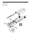
Water Meter Maintenance
The metering device used with the 960 demand controls
may require simple maintenance. In rare instances, the
turbine wheel of the water meter can collect small
particles of oxidized iron, eventually preventing the wheel
from turning.
1. Shut off the water supply or put the bypass valve(s) into
the bypass position.
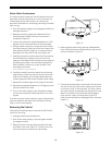
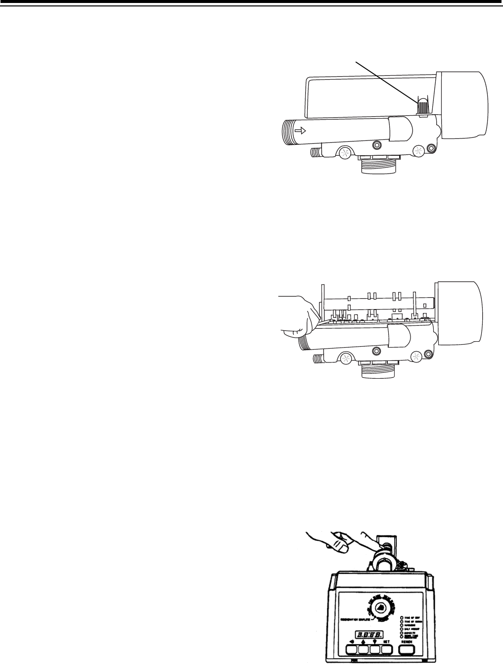
2. Relieve pressure by opening the Backwash Drain
Valve (the seventh back from the control) with a
screwdriver (Figure 9).
3. Loosen and remove the pipe/tube adapters or 1265
bypass from the inlet and outlet of the valve body.
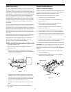
4. Using a needle-nose pliers, remove the turbine from
the outlet housing. Grasp one of the four vanes of the
outer gland and pull straight out to remove turbine
assembly from the outlet of the valve (Figure 10).
5. Carefully remove the turbine wheel from the housing.
Use a toothbrush to lightly scrub the iron off the
magnet. Iron buildup on the surfaces can be removed
by soaking the wheel in a mild sodium hydrosulfite
(such as RoVer*) solution for a few minutes. Flush
thoroughly with water.
*RoVer is a trademark of Hach Chemical Company.
6. Carefully reinstall the turbine wheel into the turbine
cage housing. Make sure that the shaft of the wheel
seats into the bearing of the cage. Reassemble the
turbine cage and check that the wheel rotates freely.
7. Reinstall the turbine cage into the outlet of the valve.
8. Reinstall the pipe/tube adapters or 1265 bypass to the
inlet and outlet of the valve.
9. Turn on the water supply or put the bypass valve(s)
into the service position and purge the air out of the
system.
To check for proper meter operation, open a downstream
faucet and observe the water flow indication, blinking
colon, on the control display.
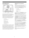
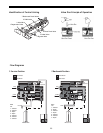
Removing the Control
Complete the following steps to remove the 960 ProSoft
control for servicing:
1. Unplug the wall-mount transformer.
2. Shut off the water supply or put the bypass valve(s)
into bypass position.
3. Remove the rear cover by depressing the two tabs
provided on the cover, Figure 11. Lift the front of the
cover and remove to expose the valve body.
Figure 11
4. Relieve system pressure by opening the Backwash
Drain Valve (the seventh valve back from the control)
with a screwdriver, Figure 12.
Figure 12
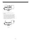
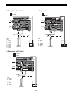
5. To remove the camshaft or to reinstall it, the arrow on
the rear of the cam shaft must be pointing at the line
on the rear “hoop” of the top plate. This occurs when
the cycle indicator is rotated to the refill position. Press
down on the back of the camshaft to disengage it
from the rear “hoop” of the top plate, Figure 13.
Slide the camshaft back to disengage it from the timer,
Figure 14.
Figure 13
Tab