


15
IO-242C 05/05
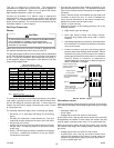
CAUTION
L
ABEL ALL WIRES PRIOR TO DISCONNECTION WHEN SERVICING CONTROLS.
W
IRING ERRORS CAN CAUSE IMPROPER AND DANGEROUS OPERATION.
V
ERIFY PROPER OPERATION AFTER SERVICING.
WARNING
T
O AVOID THE RISK OF INJURY, ELECTRICAL SHOCK OR DEATH, THE FURNACE
MUST BE ELECTRICALLY GROUNDED IN ACCORDANCE WITH LOCAL CODES OR,
IN THEIR ABSENCE, WITH THE LATEST EDITION OF THE
N
ATIONAL
E
LECTRIC
CODE.
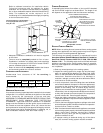
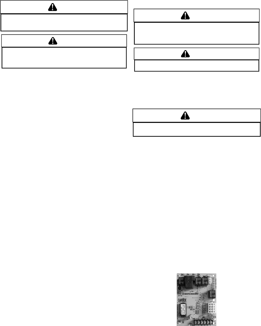
WIRING HARNESS
The wiring harness is an integral part of this furnace. Field
alteration to comply with electrical codes should not be required.
Wires are color coded for identification purposes. Refer to the
wiring diagram for wire routings. If any of the original wire as
supplied with the furnace must be replaced, it must be replaced
with wiring material having a temperature rating of at least 105° C.
Any replacement wiring must be a copper conductor.
115 VOLT LINE CONNECTIONS
Before proceeding with electrical connections, ensure that the
supply voltage, frequency, and phase correspond to that specified
on the unit rating plate. Power supply to the furnace must be NEC
Class 1, and must comply with all applicable codes. The furnace
must be electrically grounded in accordance with local codes or,
in their absence, with the latest edition of The National Electric
Code, ANSI NFPA 70 and/or The Canadian Electric Code CSA
C22.1.
Use a separate fused branch electrical circuit containing properly
sized wire, and fuse or circuit breaker. The fuse or circuit breaker
must be sized in accordance with the maximum overcurrent
protection specified on the unit rating plate. An electrical disconnect
must be provided at the furnace location.
Line voltage wiring must enter into the junction box provided with
the furnace.
NOTE: Line polarity must be observed when making field
connections.
FOSSIL F UIEL APPLICATIONS
This furnace can be used in conjunction with a heat pump in a
fossil fuel application. A fossil fuel application refers to a combined
gas furnace and heat pump installation which uses an outdoor
temperature sensor to determine the most cost efficient means
of heating (heat pump, gas furnace, or both).
A heat pump thermostat with two stages of heat is required to
properly use a furnace in conjunction with a heat pump. Refer to
the fossil fuel kit installation instructions for additional thermostat
requirements.
Strictly follow the wiring guidelines in the fossil fuel kit installation
instructions. All furnace connections must be made to the furnace
integrated control module and the FURNACE terminal strip on the
fossil fuel control board.
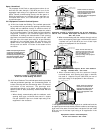
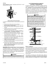
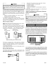
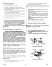
JUNCTION B OX RELOCATION
WARNING
T
O AVOID THE RISK OF INJURY, ELECTRICAL SHOCK OR DEATH, THE FURNACE
MUST BE ELECTRICALLY GROUNDED IN ACCORDANCE WITH LOCAL CODES OR,
IN THEIR ABSENCE, WITH THE LATEST EDITION OF THE
N
ATIONAL
E
LECTRIC
CODE.
WARNING
E
DGES OF SHEET METAL HOLES MAY BE SHARP.
U
SE GLOVES AS A PRE-
CAUTION WHEN REMOVING HOLE PLUGS.
Line voltage connections can be made through either the right or
left side panel. The furnace is shipped configured for a left side
electrical connection. To make electrical connections through the
opposite side of the furnace, the junction box must be relocated to
the left side prior to making electrical connections. To relocate the
junction box, perform the following steps.
WARNING
T
O PREVENT PERSONAL INJURY OR DEATH DUE TO ELECTRIC SHOCK,
DISCONNECT ELECTRICAL POWER.
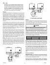
1. Remove both doors from the furnace.
2. Remove and save the screws holding the junction box to
the left side of the furnace.
3. Models that have the juction box located in the blower
compartment will need to rotate the junction box 180
degrees. Models that have the junction box located in the
burner compartment will need to move the juction box
directly over.
4. Attach the junction box to the right side of the furnace, using
the screws removed in step 2.
5. Check the location wiring. Confirm that it will not be damaged
by heat from the burners or by the rotation of the fan. Also
confirm that wiring location will not interfere with filter removal
or other maintenance.
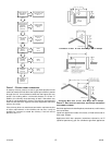
After the junction box is in the desired location, use washers to
connect field-supplied conduit to the junction box in accordance
with NEC and local codes. Connect hot, neutral, and ground wires
as shown in the furnace wiring diagram. The wires and ground
screw are located in the furnace junction box.
Low voltage wires may be connected to the terminal strip.
IMPORTANT NOTE: To avoid possible equipment malfunction,
route the low voltage wires to avoid interference with filter removal
or other maintenance.
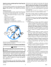
Integrated Ignition Control