


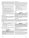
23
IO-242C 05/05
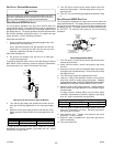
5. Turn OFF gas to furnace at the manual shutoff valve and
disconnect manometer. Reinstall plug before turning on
gas to furnace.
6. Turn OFF any unnecessary gas appliances started in step
3.
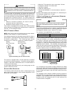
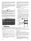
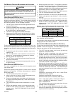
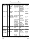
WHITE-RODGERS 36G22 GAS VALVE
The line pressure supplied to the gas valve must be within the
range specified below. The supply pressure can be measured at
the gas valve inlet pressure tap or at a hose fitting installed in the
gas piping drip leg. The supply pressure must be measured with
the unit OFF. To measure inlet pressure, use the following
procedure.
Pressure Regulator
Adjustment
(Under Cap Screw)
Gas Valve
On/Off
Selector
Switch
INLET
OUTLET
Inlet Pressure
Tap
Outlet Pressure
Tap
White-Rodgers Model 36G22
1. Turn OFF gas to furnace at the manual gas shutoff valve
external to the furnace.
2. Using 3/32 hex wrench, loosen inlet pressure tap screw
one turn.
3. Connect a 5/16 inch hose and calibrated water manometer
to the gas valve inlet pressure tap. The hose should overlap
the tap by 3/8 inch.
4. Turn ON the gas supply and operate the furnace
5. Leak test. Using a leak detection solution or non-chlorine
soap suds, check for leaks at hose connection. Bubbles
forming indicate a leak. SHUT OFF GAS AND FIX ALL LEAKS
IMMEDIATELY BEFORE PROCEEDING TO NEXT STEP!
6. Measure furnace gas supply pressure. Supply pressure
must be within the range specified in the Inlet Gas Supply
Pressure table.
If supply pressure reading differs from the table, make
necessary adjustments to pressure regulator, gas piping
size, etc., and/or consult with local gas utility.
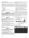
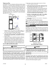
Natural Gas
Minimum: 5.0" w.c. Maximum:10.0" w.c.
Propane Gas
Minimum: 11.0" w.c. Maximum:13.0" w.c.
Inlet Gas Supply Pressure
7. Turn OFF gas to furnace at the manual shutoff valve and
disconnect manometer and hose. Reinstall plug before
turning on gas to furnace.
8. Seal pressure port. Tighten inlet pressure tap screw
clockwise 7 in-lbs. minimum.
9. Retest for leaks. If bubbles form, shut down gas and fix
leaks immediately.
10. Turn valve switch ON.
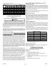
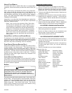
GAS SUPPLY PRESSURE MEASUREMENT
CAUTION
T
O PREVENT UNRELIABLE OPERATION OR EQUIPMENT DAMAGE, THE INLET
GAS SUPPLY PRESSURE MUST BE AS SPECIFIED ON THE UNIT RATING PLATE
WITH ALL OTHER HOUSEHOLD GAS FIRED APPLIANCES OPERATING.
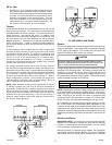
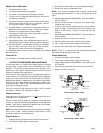
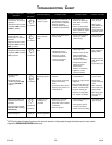
WHITE-RODGERS 36F22 GAS VALVE
The line pressure supplied to the gas valve must be within the
range specified below. The supply pressure can be measured at
the gas valve inlet pressure tap or at a hose fitting installed in the
gas piping drip leg. The supply pressure must be measured with
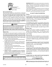
the burners operating (see picture above). To measure the gas
supply pressure, use the following procedure.
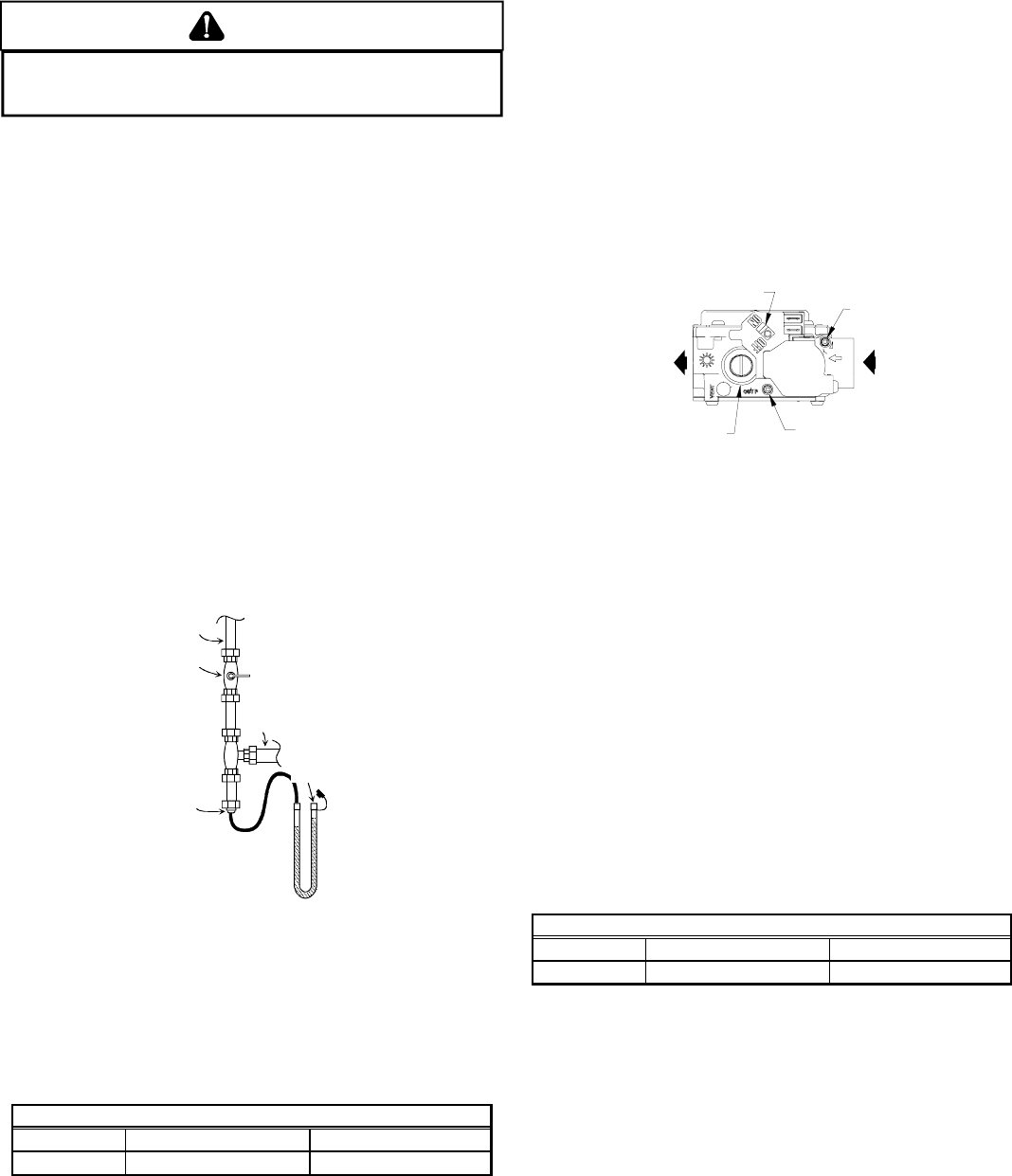
With Power and Gas Off:
1. Connect a water manometer or adequate gauge to the “inlet
pressure tap” of the gas valve.
As an alternative method, inlet gas pressure can also be
measured by removing the cap from the drip leg and
installing a predrilled cap with a hose fitting.
With Power and Gas On:
2. Put furnace into heating cycle and turn on all other gas
consuming appliances.
If operating pressures differ from the Inlet Gas Supply Pressure
table below, make necessary pressure regulator adjustments,
check piping size, etc., and/or consult with local utility.
Gas Line
Gas
Shutoff
Valve
Gas Line
To Furnace
Drip Leg Cap
With Fitting
Manometer Hose
Manometer
Open To
Atmosphere
Measuring Inlet Gas Pressure (Alternate Method)
3. Turn ON the gas supply and operate the furnace and all
other gas consuming appliances on the same gas supply
line.
4. Measure furnace gas supply pressure with burners firing.
Supply pressure must be within the range specified in the
table.
Natural Gas
Minimum: 5.0" w.c. Maximum:10.0" w.c.
Propane Gas
Minimum: 11.0" w.c. Maximum:13.0" w.c.
Inlet Gas Supply Pressure
If supply pressure differs from table, make the necessary
adjustments to pressure regulator, gas piping size, etc., and/or
consult with local gas utility.