


16
IO-242C 05/05
WARNING
T
O AVOID THE RISK OF INJURY, ELECTRICAL SHOCK OR DEATH, THE FURNACE
MUST BE ELECTRICALLY GROUNDED IN ACCORDANCE WITH LOCAL CODES OR,
IN THEIR ABSENCE, WITH THE LATEST EDITION OF THE
N
ATIONAL
E
LECTRIC
C
ODE.
To ensure proper unit grounding, the ground wire should run
from the furnace ground screw located inside the furnace junction
box all the way back to the electrical panel. NOTE: Do not use
gas piping as an electrical ground. To confirm proper unit
grounding, turn off the electrical power and perform the following
check.
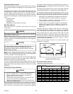
1. Measure resistance between the neutral (white)
connection and one of the burners.
2. Resistance should measure 10 ohms or less.
This furnace is equipped with a blower door interlock switch
which interrupts unit voltage when the blower door is opened for
servicing. Do not defeat this switch.
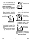
24 VOLT T HERMOSTAT WIRING
NOTE: Wire routing must not interfere with circulator blower
operation, filter removal, or routine maintenance.
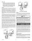
Low voltage connections can be made through either the right or
left side panel. Thermostat wiring entrance holes are located in
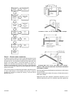
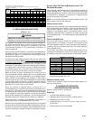
the blower compartment. The following figure shows
connections for a “heat only” system and “heat/cool system”.
Y
R
C
Y
R
C
G
W
Y
C
Furnace
Control
Furnace
Control
Remote
Condensing
Unit
Heating
Room Thermostat
Heating/Cooling
Room Thermostat
G
W
G
W
C
Y
R
R
W
Typical Field Wiring (24 VAC Control Circuit)
This furnace is equipped with a 40 VA transformer to facilitate
use with most cooling equipment. Consult the wiring diagram,
located on the blower compartment door, for further details of
115 Volt and 24 Volt wiring.
A single-stage thermostat with only one heating stage can be
used to control this furnace.
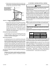
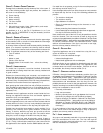
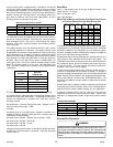
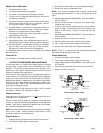
SETTING THE H EAT A NTICIPATOR
The following method should be used in measuring the amp
draw of the control circuit to assure proper adjustment of the
thermostat heat anticipator
R
R
• Wrap the “R” leg around a clip-on amp meter 10 times.
• Energize the furnace in the heat mode.
• Record the reading.
• Divide this reading by 10.
• Set the heat anticipator on the thermostat to match this
reading.
Example: If the reading on the amp meter is “4”, divide this by 10.
The anticipator setting will be .4 amps.
115 VOLT LINE CONNECTION OF ACCESSORIES (HUMIDIFIER
AND
E LECTRONIC A IR C LEANER)
WARNING
T
O AVOID PERSONAL INJURY, ELECTRICAL SHOCK OR DEATH, DISCONNECT
ELECTRICAL POWER BEFORE SERVICING OR CHANGING ANY ELECTRICAL
WIRING.
The furnace integrated control module is equipped with line
voltage accessory terminals for controlling power to an optional
field-supplied humidifier and/or electronic air cleaner.
The accessory load specifications are as follows:
Humidifier 1.0 Amp maximum at 120 VAC
Electronic Air Cleaner 1.0 Amp maximum at 120 VAC
Turn OFF power to the furnace before installing any accessories.
Follow the humidifier or air cleaner manufacturers’ instructions
for locating, mounting, grounding, and controlling these
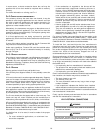
accessories. Accessory wiring connections are to be made
through the 1/4" quick connect terminals provided on the furnace
integrated control module. The humidifier and electronic air
cleaner hot and neutral terminals are identified as HUM and EAC.
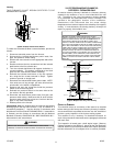
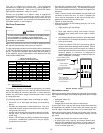
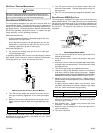
All field wiring must conform to applicable codes. Connections
should be made as shown in the following illustration.
EAC
Line
Transformer
Hum
Line
Transformer
EAC
Hum
Air Cleaner
Humidifier
Control Module
Hot 120 VAC
Neutral 120 VAC
Optional
Accessories
{
If it is necessary for the installer to supply additional line voltage
wiring to the inside of the furnace, the wiring must conform to all
local codes, and have a minimum temperature rating of 105°C.
All line voltage wire splices must be made inside the furnace
junction box.
The integrated control module humidifier terminals (HUM) are
energized with 115 volts whenever the induced draft blower is
energized. The integrated control module electronic air cleaner
terminals (EAC) are energized with 115 volts whenever the
circulator blower is energized.