25
IO-242C 05/05
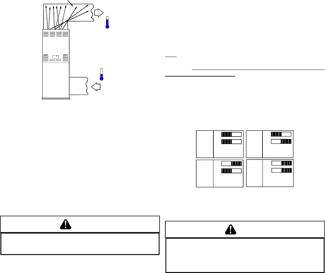
TEMPERATURE RISE
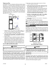
Air temperature rise is the temperature difference between supply
and return air. The proper amount of temperature rise is usually
obtained when the unit is operated at the rated input with the “as
shipped” blower speed. If the correct amount of temperature rise
is not obtained, it may be necessary to change the blower speed.
An incorrect temperature rise can cause condensing in or
overheating of the heat exchanger. Determine and adjust the
temperature rise as follows. The temperature rise must be within
the range specified on the rating plate or Product Data Book
applicable to your model*.
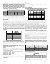
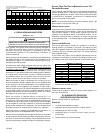
RISE =
SUPPLY
AIR
RETURN
AIR
HEAT EXCHANGER
RADIATION "LINE OF SIGHT"
T
RETURN
T
SUPPLY
T
SUPPLY
-
T
RETURN
Temperature Rise Measurement
1. Operate furnace with burners firing approximately 15
minutes. Ensure all registers are open and all duct dampers
are in their final (fully or partially open) position.
2. Place thermometers in the return and supply ducts as
close to the furnace as possible. Thermometers must not
be influenced by radiant heat by being able to “see” the
heat exchanger.
3. Subtract the return air temperature from the supply air
temperature to determine the air temperature rise. Allow
adequate time for thermometer readings to stabilize.
4. Adjust temperature rise by adjusting the circulator blower
speed. Increase blower speed to reduce temperature rise.
Decrease blower speed to increase temperature rise.
Refer to the following section for speed changing details.
CIRCULATOR B LOWER S PEED A DJUSTMENT
WARNING
T
O AVOID PERSONAL INJURY OR DEATH DUE TO ELECTRICAL SHOCK, TURN
OFF
POWER TO THE FURNACE BEFORE CHANGING SPEED TAPS.
This furnace is equipped with a PSC circulator blower motor. This
blower provides ease in adjusting blower speeds. The Product
Data Book applicable to your model provides an airflow table
showing the relationship between airflow (CFM) and external static
pressure (E.S.P.) and a table for the proper selection of heating
and cooling speeds. The cooling blower speed is shipped set on
HIGH, and the heating blower speed is set as indicated in the
Product Data Book. These blower speeds should be adjusted by
the installer to match the installation requirements so as to provide
the correct heating temperature rise and the correct cooling CFM.
To adjust the circulator blower speed, proceed as follows:
1. Turn OFF power to the furnace.
2. Select the heating and cooling blower speeds that match
the installation requirements from the airflow table in the
Product Data Book applicable to your model.
3. Relocate desired motor leads to the circulator blower heat
and cool speed terminals on the integrated control module.
(Terminals are identified as HEAT and COOL (hot)). If
heating and cooling blower speeds are the same, a jumper
wire must be used between the heat and cool terminals.
This wire is provided in the literature package.
4. Connect all unused blower motor leads to the “PARK”
terminals on the integrated control module. Any leads not
connected to the “PARK” terminals must be taped.
5. Turn ON power to furnace.
6. Verify proper temperature rise as outlined in Temperature
Rise section.
CIRCULATOR B LOWER FAN TIMING A DJUSTMENT
NOTE: Items in this section refer to the air circulator blower fan,
NOT to the induced draft blower. The induced draft blower timing
sequence is not adjustable. The circulator blower fan timing is
adjustable only on models with optional “heating fan OFF delay”
adjustment pins or switches. It is NOT adjustable in any other
circumstances.
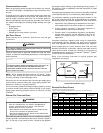
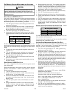
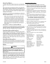
As shipped, the circulator blower fan will remain on for 90 seconds
after the gas valve closes. When a call for cooling occurs, the
circulator fan comes on and remains on for 45 seconds after the
call for cooling ends. During normal heating operation, the
circulator fan will come on approximately 37 seconds after the
gas valve opens.
O
N
O
F
F
O
N
O
F
F
O
N
O
F
F
O
N
O
F
F
1
2
1
2
1
2
1
2
90
SECOND
DELAY
120
SECOND
DELAY
150
SECOND
DELAY
180
SECOND
DELAY
Switches viewed in an upflow installation.
Adjustment Switches
XIII. OPERATIONAL CHECKS
WARNING
T
O AVOID PERSONAL INJURY OR DEATH, DO NOT REMOVE ANY INTERNAL
COMPARTMENT COVERS OR ATTEMPT ANY ADJUSTMENT.
E
LECTRICAL
COMPONENTS ARE CONTAINED IN BOTH COMPARTMENTS.
C
ONTACT A
QUALIFIED SERVICE AGENT AT ONCE IF AN ABNORMAL FLAME APPEARANCE
SHOULD DEVELOP.
BURNER FLAME
The burner flames should be inspected with the burner
compartment door installed. Flames should be stable, quiet,
soft, and blue (dust may cause orange tips but they must not be
yellow). Flames should extend directly outward from the burners
without curling, floating, or lifting off. Flames must not impinge on
the sides of the heat exchanger firing tubes.


