


24
IO-242C 05/05
GAS MANIFOLD PRESSURE MEASUREMENT AND ADJUSTMENT
CAUTION
T
O PREVENT UNRELIABLE OPERATION OR EQUIPMENT DAMAGE, THE GAS
MANIFOLD PRESSURE MUST BE AS SPECIFIED ON THE UNIT RATING PLATE.
O
NLY MINOR ADJUSTMENTS SHOULD BE MADE BY ADJUSTING THE GAS VALVE
PRESSURE REGULATOR.
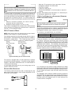
WHITE-RODGERS 36F22 GAS VALVE
Only small variations in gas pressure should be made by adjusting
the gas valve pressure regulator. The manifold pressure must be
measured with the burners operating. To measure and adjust
the manifold pressure, use the following procedure.
1. Turn OFF gas to furnace at the manual gas shutoff valve
external to the furnace.
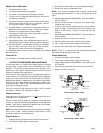
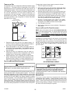
2. Connect a calibrated water manometer (or appropriate gas
pressure gauge) at the gas valve outlet pressure tap (refer
to gas valve figure in previous section).
3. Turn ON the gas supply and operate the furnace.
4. Measure gas manifold pressure with burners firing. Adjust
manifold pressure according to the Manifold Gas Pressure
table:
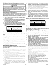
Gas Range Nominal
Natural 3.2 - 3.8" w.c. 3.5" w.c.
Propane 9.7 - 10.3" w.c. 10.0" w.c.
Manifold Ga s Pressure
The final manifold pressure must not vary more than ± 0.3 “ w.c.
from the above specified pressures. Any necessary major changes
in gas flow rate should be made by changing the size of the burner
orifice.
5. To adjust the gas valve pressure regulator, remove the
regulator cap.
6. Turn the adjustment screw clockwise to increase the
pressure, or counterclockwise to decrease the pressure.
7. Securely replace the regulator cap.
8. Turn OFF gas to furnace at the manual shutoff valve and
disconnect manometer.
9. Reinstall gas valve outlet pressure tap plug before turning
on gas to furnace.
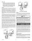
WHITE-RODGERS 36G22 GAS VALVE
This valve is shipped from the factory with the regulator preset
(see control label).
Consult the appliance rating plate to ensure burner manifold
pressure is as specified. If another outlet pressure is required,
follow these steps.
1. Turn OFF all electrical power to the system.
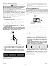
2. Using a 3/32 inch hex wrench, loosen outlet pressure tap
screw one turn. Do not remove screw.
3. Connect a calibrated water manometer and 5/16 inch hose
to the gas valve outlet pressure tap. Hose should overlap
tap by 3/8 inch.
4. Turn ON system power and set thermostat to a call for
heat.
5. Using a leak detection solution or non-chlorine soap suds,
check for leaks at hose connection. Bubbles forming
indicate a leak. SHUT OFF GAS AND FIX ALL LEAKS
IMMEDIATELY!
6. Remove regulator screw cover. Turn regulator screw either
clockwise to increase pressure or counterclockwise to
decrease. Always adjust regulator to provide the correct
pressure according to the original equipment manufacturer
specifications listed on the appliance rating plate.
7. Replace regulator screw cover and finger-tighten securely.
8. Turn OFF all electrical power to the system.
9. Remove manometer and hose from outlet pressure tap.
10. Tighten outlet pressure tap clockwise 7 in-lbs minimum to
seal port.
11. Turn ON system power and set thermostat to call for heat.
12. Using a leak detection solution or non-chlorine soap suds,
check for leaks at hose connection. Bubbles forming
indicate a leak. SHUT OFF GAS AND FIX ALL LEAKS
IMMEDIATELY!
Measure gas manifold pressure with burners firing. Adjust
manifold pressure per the Manifold Gas Pressure table.
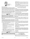
Gas Range Nominal
Natural 3.2 - 3.8" w.c. 3.5" w.c.
Propane 9.7 - 10.3" w.c. 10.0" w.c.
Ma nifold Ga s Pre ssure
The final manifold pressure must not vary more than ± 0.3 w.c.
from specified manifold pressure.
Any necessary major changes in gas flow rate should be made by
changing the size of the burner orifice.
GAS INPUT RATE MEASUREMENT (NATURAL GAS ONLY)
The gas input rate to the furnace must never be greater than that
specified on the unit rating plate. To measure natural gas input
using the gas meter, use the following procedure.
1. Turn OFF the gas supply to all other gas-burning
appliances except the furnace.
2. While the furnace is operating, time and record one
complete revolution of the smallest gas meter dial.
3. Calculate the number of seconds per cubic foot (sec/ ft
3
) of
gas being delivered to the furnace. If the dial is a one cubic
foot dial, divide the number of seconds recorded in step 2
by one. If the dial is a two cubic foot dial, divide the number
of seconds recorded in step 2 by two.
4. Calculate the furnace input in BTUs per hour (BTU/ hr).
Input equals the sum of the installation’s gas heating value
and a conversion factor (hours to seconds) divided by the
number of seconds per cubic foot. The measured input
must not be greater than the input indicated on the unit
rating plate.
EXAMPLE:
Installation’s gas heating (HTG) value: 1,000 BTU/ft
3
(Obtained from gas supplier)
Installation’s seconds per cubic foot: 34 sec/ ft
3
Conversion Factor (hours to seconds): 3600 sec/hr
Input = (Htg. value x 3600) ÷ seconds per cubic foot
Input = (1,000 BTU/ft
3
x 3600 sec/hr) ÷ 34 sec/ ft
3
Input = 106,000 BTU/hr
This measured input must not be greater than the input
indicated on the unit rating plate.
5. Turn ON gas and relight appliances turned off in step 1.
Ensure all the appliances are functioning properly and that
all pilot burners are operating.