


26
IO-242C 05/05
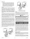
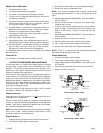
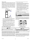
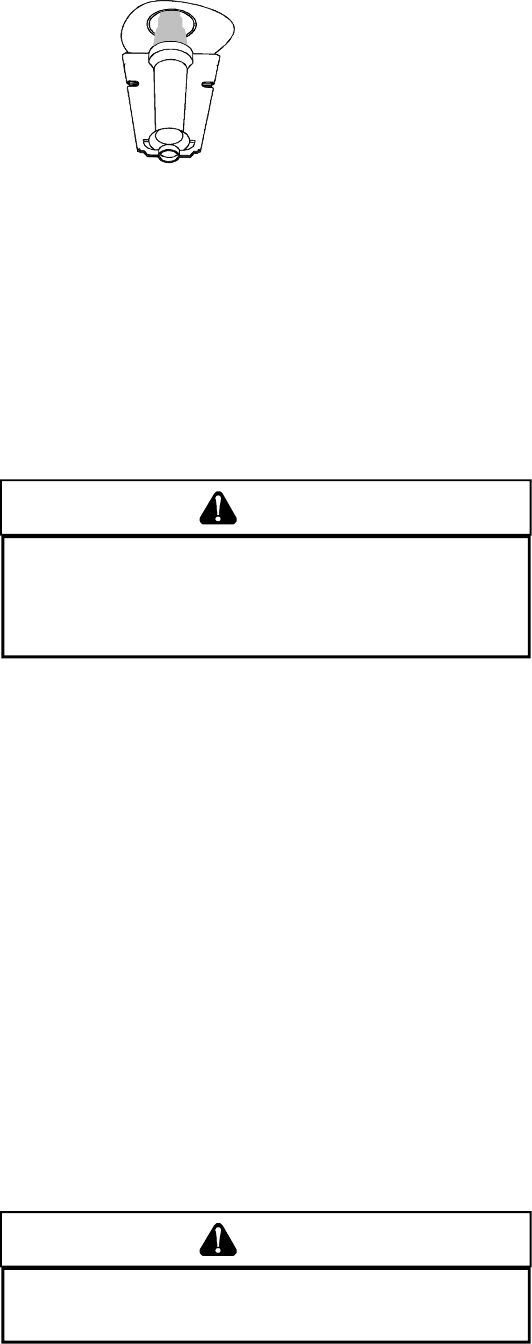
Check the burner flames for:
1. Good adjustment
2. Stable, soft and blue
3. Not curling, floating, or lifting off.
Burner Flame
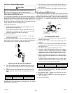
AUXILIARY L IMIT C ONTROL
Auto reset limits are located on or near the blower. To access this
auxiliary limit, disconnect the electrical power and remove the blower
door. If the limit control opens, the air circulation blower will run
continuously. The diagnostic light will flash four times. These
symptoms are identical to a trip of the primary limit control. The
auxiliary limit control is designed to prevent furnace operation in
case of main blower failure on horizontal and counterflow
installations. It may also open if the power supply is interrupted
while the furnace is firing. The auxiliary limit control is suitable for
both horizontal right and horizontal left installations. Regardless of
airflow direction, it does not need to be relocated.
WARNING
T
O AVOID PERSONAL INJURY OR DEATH, DO NOT REMOVE ANY INTERNAL
COMPARTMENT COVERS OR ATTEMPT ANY ADJUSTMENT.
E
LECTRICAL
COMPONENTS ARE CONTAINED IN BOTH COMPARTMENTS.
C
ONTACT A
QUALIFIED SERVICE AGENT AT ONCE IF AN ABNORMAL FLAME APPEARANCE
PREVENT PROPERTY DAMAGE, PERSONAL INJURY OR DEATH DUE TO FIRE,
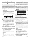
PRIMARY LIMIT
The primary limit control guards against overheating resulting
from insufficient conditioned air passing over the heat exchanger.
If the primary limit control does not function during this test, the
cause must be determined and corrected. Function of this control
should be verified by gradually blocking the furnace return air after
the furnace has been operating (burners firing) for approximately
ten minutes. Check the control as follows:
1. Allow the furnace to operate with burners firing continuously
for approximately ten minutes.
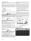
2. Gradually block the return air to furnace. Remove airflow
blockage when limit control is activated and turns off burners.
Airflow blockage causes unit overheating and will produce
the following reactions:
• The gas valve to close and extinguish flame,
• The induced draft blower to be de-energized after a fifteen
second postpurge, and
• The circulator blower to remain energized continuously until
limit control resets.
3. Remove the return air blockage to clear overheating
condition. After an acceptable temperature is reached
during the cool down period, the limit control will reset and
allow the furnace to resume normal operation.
WARNING
T
O PREVENT PREMATURE FAILURE OF HEAT EXCHANGER, PROPERTY DAMAGE,
PERSONAL INJURY OR DEATH, DO NOT ADJUST THE LIMIT CONTROL (FACTORY
SET).
IMPORTANT NOTE: This unit must not be used as a construction
heater during the finishing phases of construction of a new
structure. This type of use may result in premature failure due to
extremely low return air temperatures and exposure to corrosive
or very dirty atmospheres.
These checks establish that the primary limit control is functioning
and will respond to a restriction in the return air, or a circulator
blower failure. If the primary limit control does not function during
this test, the cause must be determined and corrected.
XIV. SAFETY CIRCUIT DESCRIPTION
GENERAL
A number of safety circuits are employed to ensure safe and proper
furnace operation. These circuits serve to control any potential
safety hazards and serve as inputs in the monitoring and diagnosis
of abnormal function. These circuits are continuously monitored
during furnace operation by the integrated control module.
INTEGRATED C ONTROL M ODULE
The integrated control module is an electronic device which
controls all furnace operations. Responding to the thermostat,
the module initiates and controls normal furnace operation, and
monitors and addresses all safety circuits. If a potential safety
concern is detected, the module will take the necessary
precautions and provide diagnostic information through an LED.
PRIMARY LIMIT
The primary limit control is located on the partition panel and
monitors heat exchanger compartment temperatures. It is an
automatic reset, temperature sensor. The limit guards against
the overheating as a resulting of insufficient air passing over the
heat exchanger.
AUXILIARY L IMIT
The auxiliary limit control is located either on or near the circulator
blower and monitors heat exchanger compartment temperatures.
The control is a temperature sensor. It guards against overheating
resulting from insufficient air passing over the heat exchanger.
ROLLOUT L IMITS
The rollout limit controls are mounted on the burner/manifold
assembly and monitor the burner flame. They are manual-reset,
temperature sensors. This limit guards against burner flames not
being properly drawn into the heat exchanger.
PRESSURE SWITCHES
The pressure switches are normally-open, negative air pressure-
activated switches. They monitor the airflow (combustion air and
flue products) through the heat exchanger via pressure taps located
on the induced draft blower. These switches guard against
insufficient airflow (combustion air and flue products) through the
heat exchanger.
FLAME SENSOR
The flame sensor is a probe mounted to the burner/manifold
assembly which uses the principle of flame rectification to
determine the presence or absence of flame.
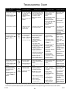
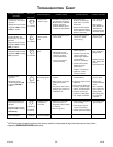
XV. TROUBLESHOOTING
ELECTROSTATIC D ISCHARGE (ESD) PRECAUTIONS
NOTE: Discharge body’s static electricity before touching unit. An
electrostatic discharge can adversely affect electrical components.