


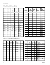
Installation
16 3A0237L
Installation
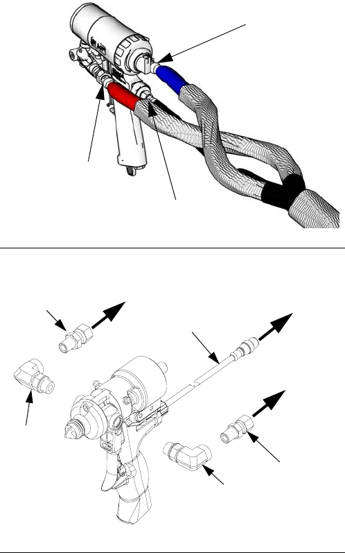
Description
The heated hose maintains proper fluid temperature
while dispensing.
Fluid hoses are marked with red tape for ISO/hard-
ener/minor volume side, blue tape for RES/resin/major
volume side. Fittings have different sized threads to pre-
vent incorrect connection, which can cause fluid cross-
over and permanently damage the hose.
Hoses are 5 ft (1.5 m), 10 ft (3 m), 25 ft (7.6 m), and 50 ft
(15.2 m) long. The whip hose is 5 ft (1.5 m) or 10 ft (3 m)
long.
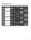
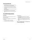
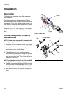
Connect Whip Hose to Gun or
Gun Manifold
NOTE: For best whip hose flexibility, assemble whip
hose to gun or gun manifold as instructed.
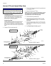
1. Assemble A and B component hoses to gun or gun
manifold fittings as shown in F
IG. 1 and FIG. 2.
2. If applicable, assemble signal cable (E1) and air
hose to gun or gun manifold fittings.
3. Tighten fittings to A and B component hoses.
Ensure hose remains flat after fittings are tightened.
Loosen and retighten fittings as necessary to elimi-
nate any torque on hoses. This will help achieve a
flat profile on the hose.
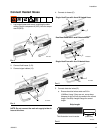
NOTE: Use chemical connection kit (153) on all MD2
valves. See F
IG. 2.
4. For MD2 valves with 255208 and 255249 and both
EP Gun models, connect the signal cable (E1) from
the applicator to the whip hose signal cable (3b).
5. See applicator manual for complete setup instruc-
tions.
F
IG. 1: Fusion Gun
F
IG. 2: MD2 Valve Kit 24D501
Tighten
Tighten
Tighten
r_24d501_3a0237_1a
153a
153b
A Side Hose
E1
3b
B Side Hose
153a
153c