


Installation
3A0237L 17
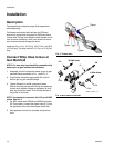
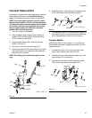
Connect Heated Hoses
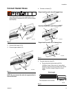
1. Lay heated hoses end to end, matching the color
coding. Red for component A (ISO), blue for compo-
nent B (RES).
2. Connect fluid hoses (A, B).
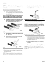
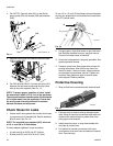
3. Connect signal cables (13).
NOTE: Do not connect the main air supply to the air
hose at this time.
4. Connect air hoses (C).
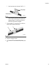
5. Connect electrical wires (D).
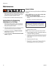
a. Ensure electrical wires ends are 5/8 in.
(0.625mm) long. If they are not, use a sharp
scissors to strip all four wire ends to the correct
length. See Strip Length Gauge for correct
length.
FIG. 3
F
IG. 4
A
B
TI14731a
TI14732a
B
A
13
FIG. 5
F
IG. 6
C
TI14733a
D
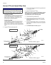
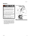
Single Heat Zone with A and B Heated Hose
Dual Heat Zone with A and B Heated Hose
TI15097a
C
D
D
Single Heat Zone with A or B Heated Hose
C
D
D
TI15140a
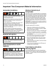
Strip Length
5/8 in.
TI9733a
(0.625 mm)
This illustration is not to scale.