


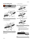

Installation
3A0237L 21
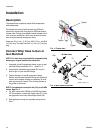
Connect Solenoid Kit
A solenoid kit is required for some applicators used with
Graco Metering Systems. See Individual Hoses on
page 5 to see which applicators require a solenoid kit.
NOTE: To ensure proper operation of valve, install
the solenoid kit within 15 ft (4.5 m) of the applicator.
The solenoid reaction time decreases if the solenoid
kit is farther away from the applicator. Ensure that
the scuff guard covers the solenoid if mounted
between the hose and whip hose.
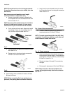
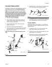
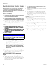
1. Turn off all power to the system.
2. Apply anaerobic pipe sealant to pipe threads on
mufflers (205), tee fitting (202), and swivel fitting
(215). Connect to valve (201).
3. Connect elbow fittings (204), and wire harness
(206) to valve (201).
4. Connect air hose (C) to swivel fitting (215).
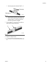
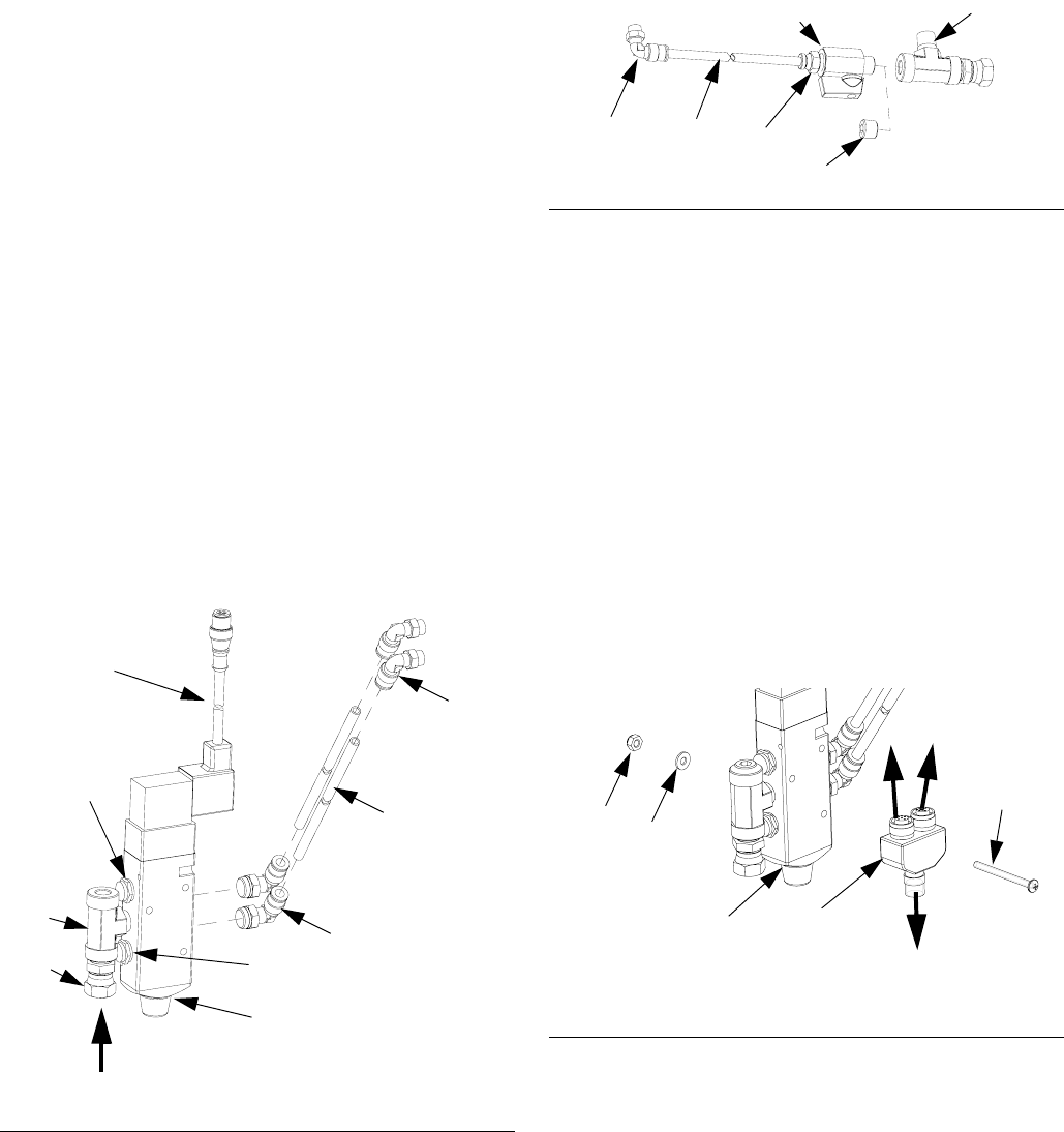
5. Connect two elbows (207) and tubing (212) to open
and closed ports on the applicator. See applicator
manual for port locations.
NOTE: Cut tubing (212) to desired length if neces-
sary.
6. Install plug (203), or tube fitting (214) and ball valve
(213) in the other side of the tee fitting (202).
7. For solenoid kit 24D161: Connect elbow fitting (207)
and tubing (212) to the purge air port and tube fitting
(214). See applicator manual for port locations.
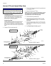
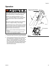
Connect Splitter
24D160 and 24D161 use a splitter (211) to allow the
Graco Metering System to dispense material from the
system controls.
1. Connect the splitter (211) to the valve (201) with
screw (208), washer (209), and nut (210).
2. Connect the hose communications cable (24) to the
single splitter (211) connection.
3. Connect the wire harness (206) and signal cable
(3b) from the whip hose to the splitter (211).
F
IG. 14
202
207
212
204
201
205
r_24D161_3a0237b_1
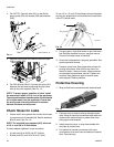
b
205
206
C
215
F
IG. 15
F
IG. 16
214
203
202
212207
r_24D161_3a0237B_2b
213
211
208
210
209
24
3b
206
201
r_24D160_3a0237b_1b