


Installation
20 3A0237L
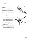
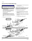
Connect FTS and Heated Whip Hose
1. For Single Zone Heat:
Carefully extend FTS probe (H) into the hose sec-
tion from the proportioner. Do not bend or kink
probe. Insert in component A (red) side of main
hose for foam or polyurea systems.
For Dual Zone Heat:
Carefully extend FTS probe (H) into the hose sec-
tions from the proportioner. Do not bend or kink
probe. Insert in component A (red) and component
B (blue) side of main hose for foam or polyurea sys-
tems.
2. Connect FTS (J) to whip hose (W).
3. Connect whip hose ground wire (K) to ground screw
on underside of FTS.
4. Connect fluid hoses to FTS (J).
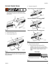
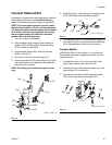
NOTE: To use 1/2 in. (13 mm) ID fluid hoses, remove
the adapters from the proportioner fluid manifold
and install them in the FTS swivel inlets.
5. Connect electrical connectors (D).
6. Connect air hose (C) to whip air hose (L) or see
Connect Solenoid Kit on page 21 for installation
instructions.
7. Connect hose assembly cable (F) to FTS cable (R).
Leave slack (G) in cables as stress relief, to prevent
cable failure.
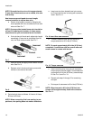
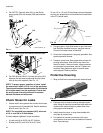
8. See Check Hoses for Leaks, page 22.
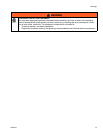
NOTICE
To prevent damage to probe, do not kink or exces-
sively bend hose. Do not coil hose tighter than the
minimum bend radius of 3 ft (0.9 m). Do not subject
hose to excessive weight, impact, or other abuse.
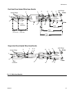
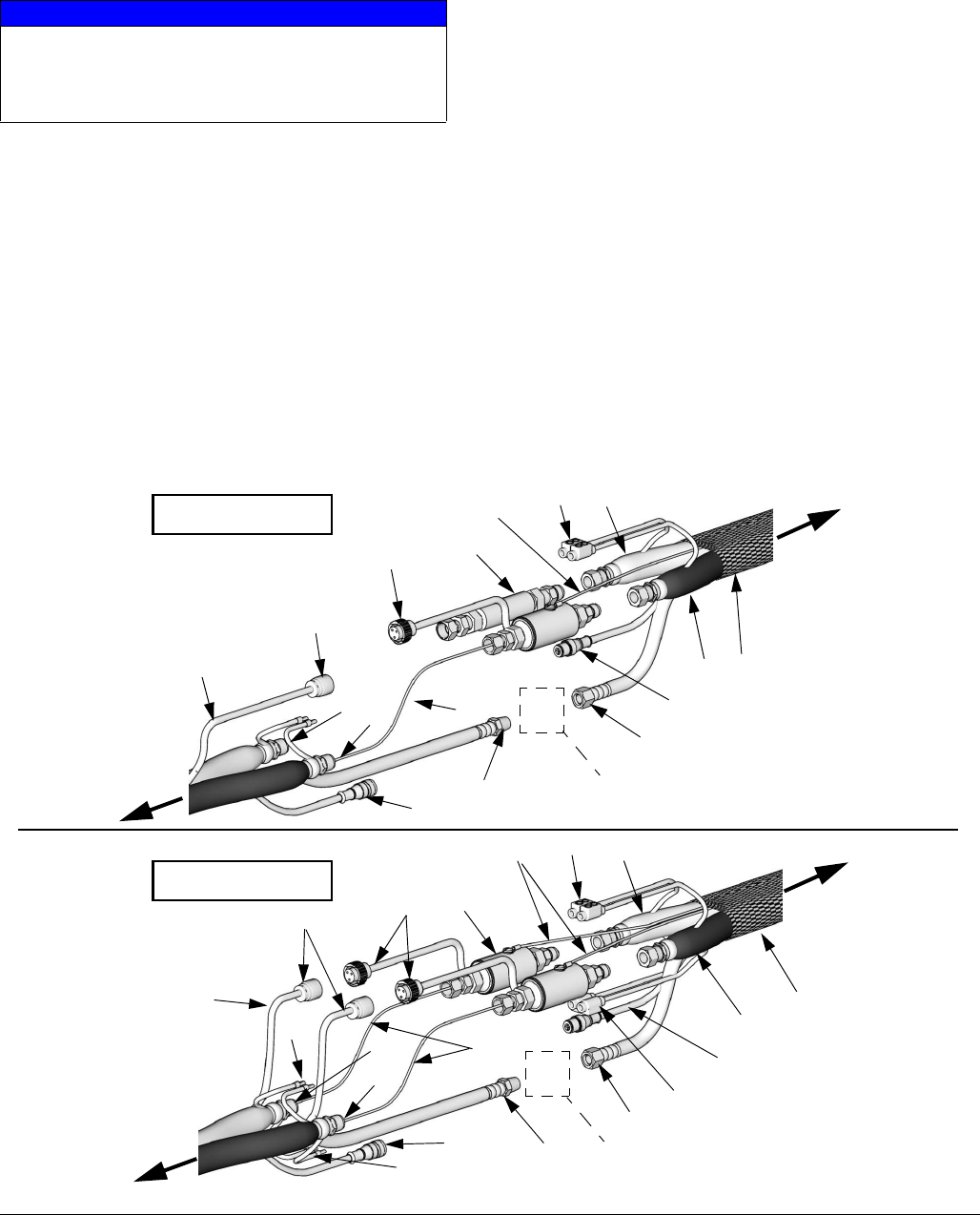
FIG. 13: FTS Connections
B
A
A
B
K
H
C
D
J
L
F
G
W
R
To Gun
To Proportioner
A
B
K
H
C
D
J
L
F
G
W
R
24D160 or 24D161, page 21
24D160 or 24D161, page 21
3b
24
To Gun
To Proportioner
Single Zone Heat
B
A
24
3b
D
ti14736b
ti14735a
D
D
Dual Zone Heat