


14
®
Model MSX Make-Up Air
for one minute, the system is ready to be charged or
refrigerant in another portion of the system can be
opened to the coil. A steady rise in microns would
indicate that moisture is still present and that the coil
should be further vacuumed until the moisture has
been removed.
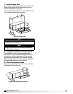
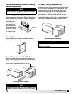
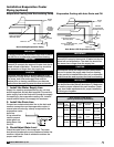
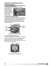
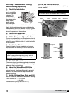
8. Install the Drain Line
Connect an
unobstructed drain
line to the drain
pan. A trap should
be used to prevent
sewer gas from being
drawn into the unit.
NOTE
Failure to obtain a high vacuum indicates a great
deal of moisture or a small leak. Break the vacuum
with a charge of dry nitrogen or other suitable
gas and recheck for leaks. If no leaks are found,
continue vacuuming the coil until the desired
vacuum is reached.
IMPORTANT
All traps must be installed below the roof line or be
otherwise protected from freezing.
6 in. min.
6 in. min.
Drain Trap
6 in. min.
6 in. min.
Drain
Trap
Installation of Chilled Water Coil
Piping (optional)
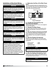
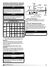
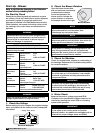
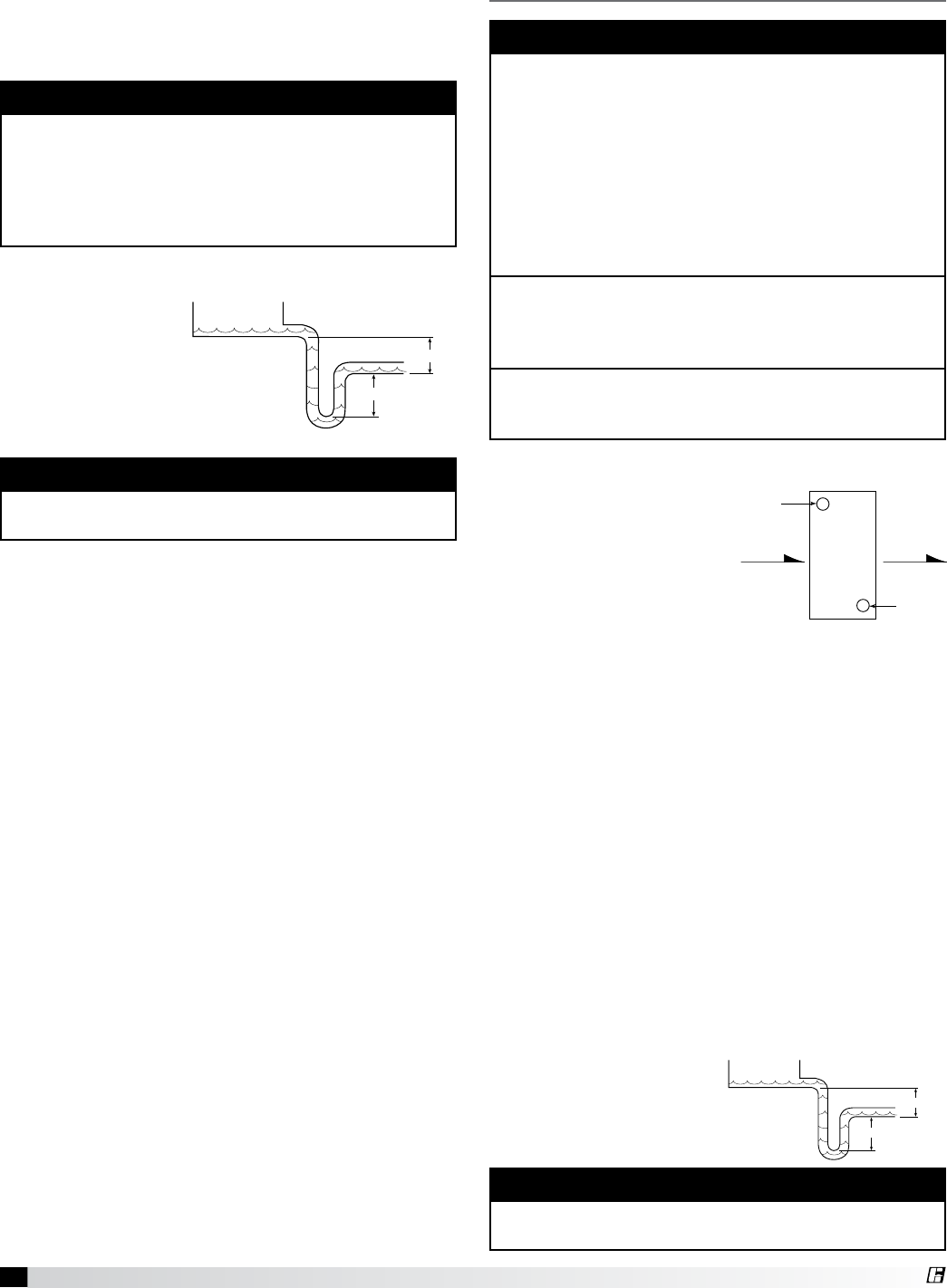
1. Verify Coil Hand Designation
Check the coil hand
designation to ensure that
it matches the system.
Coils are generally
plumbed with the supply
connection located on
the bottom of the leaving
air-side of the coil and the
return connection at the top of the entering air-side
of the coil. This arrangement provides a counter flow
heat exchanger and positive coil drainage.
2. Check the Coil for Leaks
Pressurize the coil to 100 psig with dry nitrogen or
other suitable gas. The coil should be left pressurized
for a minimum of 10 minutes. If the coil holds the
pressure, the hook-up can be considered leak free.
If the pressure drops by 5 psig or less, re-pressurize
the coil and wait another 10 minutes. If the pressure
drops again there is likely one or more small leaks
which should be located and repaired. Pressure losses
greater than 5 psig indicate a large leak that should be
isolated and repaired.
3. Connect the Supply and Return Lines
Connect the supply and return lines as shown above.
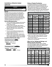
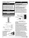
4. Install the Drain Line
Connect an unobstructed
drain line to the drain pan.
A trap should be installed
to prevent sewer gas from
being drawn into the unit.
Hot Return
Connection
Cold Supply
Connection
Entering Air Leaving Air
IMPORTANT
Guidelines for the installation of the cooling coil
have been provided to insure proper performance
of the coils and their longevity. These are general
guidelines that may have to be tailored to meet the
specific requirements of any one job. As always,
a qualified party or individual should perform the
installation and maintenance of the coil. Protective
equipment such as safety glasses, steel toe boots
and gloves are recommended during the installation
and maintenance of the coil.
When installing couplings, do not apply undue
stress to the connection. Use a backup pipe
wrench to avoid breaking the weld between the coil
connection and the header.
All field piping must be self-supporting. System
piping should be flexible enough to allow for the
thermal expansion and contraction of the coil.
IMPORTANT
All traps must be installed below the roof line or be
otherwise protected from freezing.