


24
®
Model MSX Make-Up Air
Operation - Electrical
Electrical Sequence
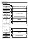
1. Exhaust Fan Contact (S1) Closed
(optional)
• Power passes through N.C. contact on exhaust
fan overload (ST2 OL), which is closed if
exhaust fan (M2) has not overloaded
• Power passes to exhaust fan starter (ST2)
• N.O. contact on exhaust fan starter (ST2) is
energized and closed
• Power passes to exhaust fan
• Exhaust fan (M2) starts
2. Supply Fan Contact (S2) Closed
• Power passes through N.C. eld supplied re
contact (FSC)
• Power passes through optional N.O. contact on
exhaust fan starter (ST2), which is closed when
the optional exhaust starter (ST2) is activated
• Power passes through N.C. contact on supply
starter overload (ST1 OL), which is closed if the
supply fan has not overloaded
• Power passes through N.C. contact on optional
freeze protection timer (RT4) which remains
closed if the temperature has remained above
the set point
• Power passes to and energizes optional inlet
damper (D1), which opens
• Power passes through optional N.O. damper
limit switch (DL1), which is energized and
closed when the optional inlet damper is open.
It may take several minutes for the damper to
fully open and for the damper limit switch to
close
• Power passes to and energizes fan relay (RF)
• Power passes through N.O. contact on fan relay
(RF), which closes when the fan relay (RF) is
energized
• Power passes to and energizes supply fan
starter (ST1)
• N.O. contact on supply fan starter (ST1) is
energized and closed
• Supply fan (M1) starts
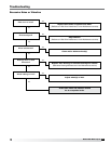
3. Electric Heat Contact (S4) Closed
(optional)
• Power passes through N.O. contact on fan relay
(RF), which is energized and closed
• Power passes through N.C. contact on optional
inlet air sensor (TS4), which is closed if the inlet
air temperature is below the set point
• Power passes to and energizes heat relay (RH)
• Power passes through N.O. contact on heat
relay (RH), which closes when the heat relay
(RH) is energized
• Power passes through N.O. contact on pressure
differential switch (PDS), which closes when
proper airflow is achieved
• Power passes through N.C. automatic and
manual reset temperature cutouts (A and
M), which remain closed if the maximum
temperature has not been reached
• Power passes to and energizes operating
contactor relay (C1)
• Power passes through N.O. contacts on
operating contactor (C1), which is closed
• Electric heater modulates/stages to maintain
temperature set point
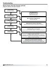
4. Evaporative Cooling Contact (S4)
Closed* (optional)
• N.O. contact on fan relay (RF) is energized and
closed
• Power passes through N.O. contact on optional
inlet air sensor (TS4), which is energized and
closed if the inlet air temperature is above the
set point
• Power passes to and energizes cool relay (RC)
• N.O. contact on cool relay (RC) is energized and
closed
• Power passes to optional evaporative cooling
pump (P1)
*If DX or chilled water coils are used rather than an evaporative
cooler, the cooling sequence of operation will depend on the coil
controls. Cooling coil controls are supplied by others.