


19
®
Model MSX Make-Up Air
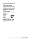
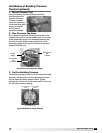
1. Check the Installation
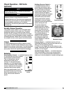
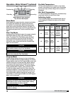
The media may have been removed during installation,
so its orientation
should be double
checked. The
media should
be installed with
the steeper flute
angle sloping
down towards
the entering air
side.
Verify that the stainless steel caps and distribution
headers are in place. The headers should be located
over the media towards the entering air side. The caps
should be placed over the headers.
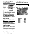
2. Check the Pump Filter
Check that the pump filter is around the pump inlet.
3. Fill the Sump and Adjust the Float
Turn on the water supply and allow the sump tank to
fill. Adjust the float valve to shut-off the water supply
when the sump is filled to within 1 inch of the bottom
of the overflow.
4. Break-in the Media
Open the bleed-off valve completely and saturate
the media with the blower(s) off for no less than 20
minutes.
5. Check the Flow Rate
The pumps should provide enough water to saturate
the media in 45 to 60 seconds. Consult the factory, if
adequate flow is not achieved.
6. Adjust the Water Bleed-Off Rate
The water bleed-off rate is dependent on the water’s
mineral content. The bleed-off should be adjusted
based on the media’s mineral deposits after two
weeks of service.
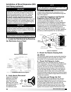
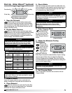
7. Set the Optional Auto Drain and Fill
Set the auto drain, fill timer and temperature settings.
Timer settings are: t1: 1.0, 10min
t2: 0.4, 60h
Temperature is typically set to 45°F (7°C)
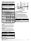
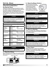
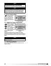
Start-Up - Evaporative Cooling
Recirculating (optional)
Bleed-Off
Valve
Overflow
Pump
Filter
Threaded Float
Adjustment
Supply
Connection
Float
Valve
Evaporative
Timer
t2 settings
t1 settings
Evaporative Freeze
Protection
Temperature
Setting
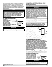
8. Put the Unit into Service
Remove the jumper, and energize the blower(s). Verify
proper operation.
IMPORTANT
Check the media for minerals after two weeks of
service and adjust the bleed-off rate accordingly.
Leaving Air
Entering Air
45º
15º
Media Orientation
Evaporative Cooler Set-Up
NOTE
A jumper will need to be installed in the control
center to power the evaporative pumps with the
blower(s) off. Reference the unit’s ladder diagram to
determine proper terminals.