


3
®
Model MSX Make-Up Air
Table of Contents
Installation
Clearance to Combustibles/Service Clearances . 3
Indoor Unit ............................... 3
Unit Arrangement DB / HZ / UB .............. 4
Roof Mounted Unit — Arrangement DBC .....5-6
Optional Evaporative Cooling Module ......... 7
Electrical Wiring .......................... 8
Optional Electrical Heater ................... 9
Optional Evaporative Cooling Piping .......10-11
Optional Water Wizard™ .................. 12
Optional Direct Expansion (DX) Coil Piping ..13-14
Optional Chilled Water Coil Piping ........... 14
Optional Building Pressure Control .......... 15
Start-Up
Blower ...............................16-17
Optional Electric Heater ................... 18
Optional Evaporative Cooling Recirculating ... 19
Optional Water Wizard™ ................20-21
Operation
Optional VAV Units ....................... 22
Optional Recirculating Units ................ 23
Electrical ............................... 24
Optional Water Wizard™ .................. 25
Troubleshooting
Blower ................................. 26
Motor Overamps ......................... 27
Insufficient / Too Much Airflow .............. 28
Excessive Noise or Vibration ............... 29
Optional Electric Heater ................... 30
Optional Evaporative Cooling ............... 31
Optional Water Wizard™ .................. 32
Maintenance
Routine ..............................33-35
Fall .................................... 36
Reference
Control Center Layout / Dirty Filter Switch .... 37
Start-Up Check List ...................... 38
Maintenance Log ........................ 39
Warranty .........................Backcover
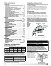
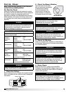
Clearance to Combustibles /
Service Clearances
Floor Top Sides Ends
Insulated/
Units
0 inches
(0 mm)
0 inches
(0 mm)
0 inches
(0 mm)
0 inches
(0 mm)
Non Insulated
Units
0 inches
(0 mm)
6 inches
(152.4 mm)
6 inches
(152.4 mm)
6 inches
(152.4 mm)
Clearance to combustibles is defined as the minimum distance
required between the heater and adjacent combustible surfaces to
ensure the adjacent surface’s temperature does not exceed 90 degrees
above the ambient temperature.
Recommended Minimum Service Clearances
Housing 32 and less
42 inches (1066.8 mm)
on the controls side of the unit
Housing 35 and higher
48 inches (1219.2 mm)
on the controls side of the unit
Clearances for component removal (such as evaporative cooler media)
may be greater than the service clearances listed.
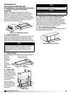
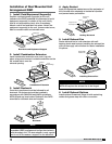
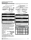
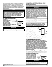
Installation of Indoor Unit
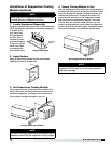
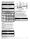
3. Seal Wall Opening
Apply sealant around
the perimeter of the
weatherhood to prevent
water penetration and
drafts into the building.
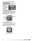
1. Install Hangers
Install threaded hangers from ceiling supports. When
locating hangers, allow enough room to open access
panel(s). Two nuts must be used on the end of each
threaded hanger. Ceiling supports are supplied by
others.
2. Install Unit
Using sheet metal screws, attach the weatherhood/
thru-wall/filter section to the blower/burner section.
The flange on the weatherhood/thru-wall/filter section
should overlap the flange on the blower/burner section.
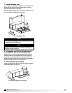
Raise the assembled unit into place.
Using two nuts per hanger, fasten the unit supports to
the hangers under the unit. Appropriate unit supports,
such as the optional Greenheck hanging bracket kit or
c-channel and angle iron (supplied by others) should be
used.
Using self
tapping
screws,
attach
ductwork to
unit.
In order to
prevent the
unit from
swinging
and to
provide
a safe
environment for service and maintenance, additional
measures must be taken to secure the unit in all
directions.
Unit Supports
Ceiling Supports
Hangers
Ductwork
NOTE
Two nuts must be used on each end of each
threaded hanging rod for proper support.
NOTE
Good duct practices should be followed for
all ductwork. Ductwork should be installed in
accordance with SMACNA and AMCA guidelines,
NFPA 96 and any local codes. Reference the CAPS
submittal for duct sizes.
Indoor Mounting
Sealant
Seal Wall Opening