


8
®
Model MSX Make-Up Air
Installation of Electrical Wiring
IMPORTANT
Before connecting power to the unit, read and
understand the following instructions and wiring
diagrams. Complete wiring diagrams are attached
on the inside of the control center door(s).
IMPORTANT
All wiring should be done in accordance with the
latest edition of the National Electric Code ANSI/
NFPA70 and any local codes that may apply. In
Canada, wiring should be done in accordance with
the Canadian Electrical Code.
IMPORTANT
The equipment must be properly grounded. Any
wiring running through the unit in the airstream must
be protected by metal conduit, metal clad cable or
raceways.
CAUTION
If replacement wire is required, it must have a
temperature rating of at least 105°C, except for an
energy cut-off or sensor lead wire which must be
rated to 150°C.
DANGER
High voltage electrical input is needed for this
equipment. This work should be performed by a
qualified electrician.
CAUTION
Any wiring deviations may result in personal injury
or property damage. Greenheck is not responsible
for any damage to, or failure of the unit caused by
incorrect final wiring.
IMPORTANT
Greenheck’s standard control voltage is 24VAC.
Control wire resistance should not exceed
0.75ohms (approximately 285 feet total length for
14gauge wire; 455 feet total length for 12gauge
wire). If the resistance exceeds 0.75 ohms, an
industrial-style plug-in relay should be wired in
place of the remote switch. The relay must be
rated for at least 5 amps and have a 24 VAC coil.
Failure to comply with these guidelines may cause
motor starters to chatter or not pull in, resulting in
contactor failures and/or motor failures.
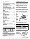
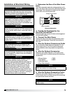
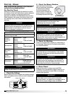
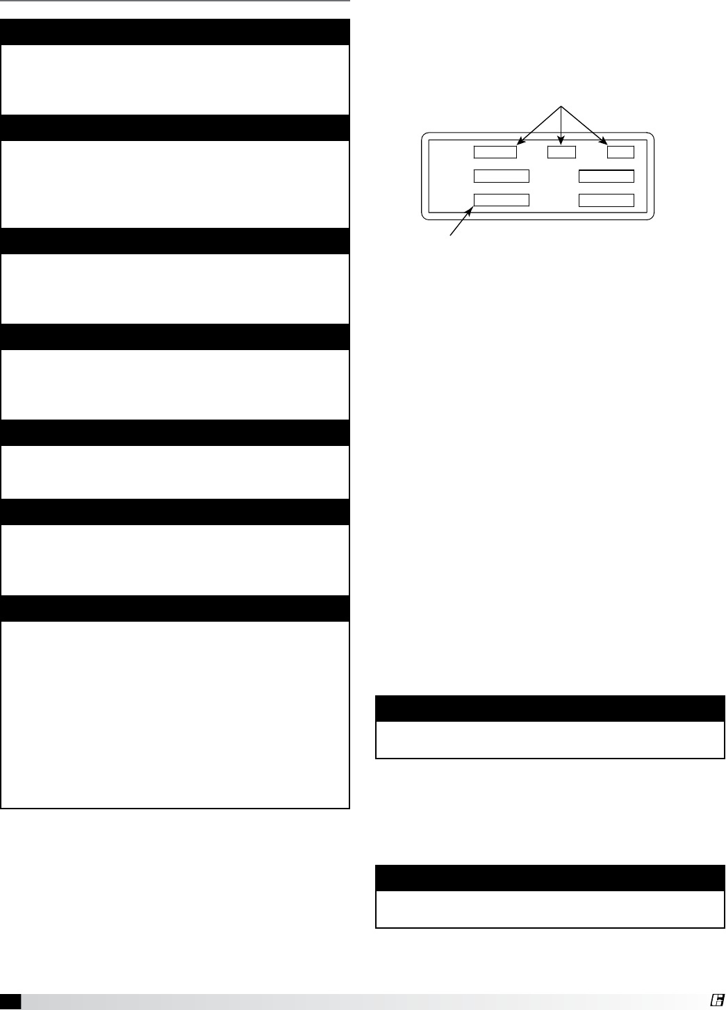
1. Determine the Size of the Main Power
Lines
The unit’s nameplate states the voltage and the unit’s
MCA. The main power lines to the unit should be sized
accordingly. The nameplate is located on the outside
of the unit on the control panel side.
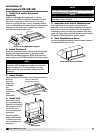
2. Provide the Opening(s) for the
Electrical Connections
Electrical openings vary by unit size and arrangement
and are field supplied.
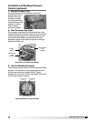
3. Connect the Main Power
Connect the main power lines to the disconnect switch
and main grounding lug(s). Torque field connections to
20in.-lbs.
4. Wire the Optional Convenience Outlet
The convenience outlet requires a separate 115 volt
power supply circuit. The circuit must include short
circuit protection which may need to be supplied by
others.
5. Wire the Optional Accessories
Reference the Ladder Diagram on the inside of the
control center door for correct wiring of the following
accessories:
• Blower Switch
• Heat Switch
• Indicating Lights
• Dirty Filter Indicator
• TSCP
• KSCP
NOTE
TSCP has number-to-number wiring.
NOTE
Large evaporative coolers may require a separate
power supply.
6. Wire the Optional Evaporative Cooler
Reference the Ladder Diagram on the inside of the
control center door for correct wiring of the pump and
the optional auto-drain and flush.
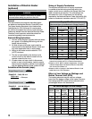
SUP HP
MCA
EXH HP
MOP
VOLTS HZ PH
Unit’s Total MCA
Voltage, Hertz, Phase
SUP HP
MCA
EXH HP
MOP
VOLTS HZ PH
Voltage, Hertz, Phase
Electrical Nameplate