


Model PFE- 590/592
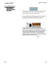
3-1. OPERATING COMPONENTS
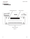
POWER/PUMP Switch A three way switch with center OFF position; move the switch to
the position marked POWER to operate the fryer; move the switch
to the position marked PUMP to operate the filter pump; certain
conditions must be met prior to operation of the filter pump; these
conditions are covered later in this section
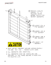
Frypot This reservoir holds the cooking shortening, and is designed to
accommodate the heating elements, 8 head of product and an
adequate cold zone for collection of cracklings
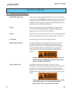
Carrier This stainless steel carrier consists of five racks, containing the food
product during and after frying (4 cook racks and 1 cover rack)
Lid Gasket Provides the pressure seal for the frypot chamber
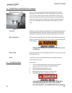
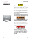
Deadweight assembly The deadweight style operating pressure relief valve is used to
maintain a constant level of steam pressure within the frypot;
any excess steam pressure is vented through the exhaust stack;
remove the deadweight cap, and clean the cap, weight, and
deadweight orifice once a day. See Preventive Maintenance
Section.
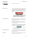
Failure to clean the deadweight assembly daily could
result in the fryer building too much pressure. Severe
injuries and burns could result.
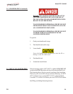
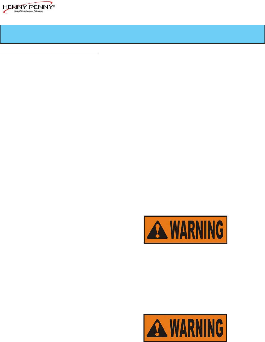
Safety Relief Valve An ASME approved spring loaded valve set at 14.5 psi
(999 mbar); in the event the operation valve becomes obstructed,
this safety valve releases excess pressure, keeping the frypot
chamber at 14.5 psi (999 mbar); if this occurs, turn the COOK/
PUMP switch to the OFF position to release all pressure from the
frypot
If safety relief valve activates, turn main power switch
to the OFF position. To avoid serious burns and
injuries, have fryer serviced before next use.
3-1 703
SECTION 3. OPERATION