


– 12 –
Fans and Defrost Heaters
Bring all connector blocks from the coil and fan section (fans and defrost heaters) up through
TUBE #3
and TUBE #4 to the electrical box (refer to Fig. 8, page 8). Mate the connector blocks with matching
connector blocks from the ceiling electrical box. Seal
TUBE #3 and TUBE #4 around the wires with proper
insulation. Duct seal (putty) is supplied with the cabinet.
If an optional rear pass-thru door is included, connect the additional mating connector blocks for the
door switch and door perimeter heater wires.
REFRIGERATION CONNECTIONS
On top-mounted, self-contained HQC135, all refrigeration lines are of the proper length. Assemble by
connecting the quick couplers. Brazing and welding are not required. Lines are pre-charged with
R-404A refrigerant.
On cabinets with remote condensing units, proceed with all refrigeration brazing that needs to be done
to bring suction and liquid lines out of the cabinet interior. Bring liquid line from the interior to the
solenoid valve installed on top of the cabinet. On standard units, refrigeration lines go out through the
ceiling hole. Seal hole around the lines with proper insulation. Duct Seal (putty) is supplied with the
cabinet.
Suction and liquid lines have to be installed between the cabinet and the remote compressor.
Refrigeration installation and start-up must then be done by a professional refrigeration technician,
using recognized industry-standard procedures.
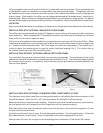
DRAIN LINE INSTALLATION
The drain tube begins at the
7
/8" O.D. stainless steel connection at the bottom of the drain pan,
underneath the coil and fan section. If the drain outlet was not selected and drilled, make a hole in the
wall panel to exit the drain line. From the stainless steel connection, the drain should either go straight
to the front, straight to the rear, or straight to the side. Sufficient copper pipe is supplied to exit the
cabinet. Install this copper pipe by attaching it to the stainless steel connection using a small self-
tapping screw.
Once the drain exits the cabinet, it must be trapped per local code before being extended to an open
floor drain. The clearance area around the drain tube where it exits the panel wall must be sealed with
an NSF approved sealer.
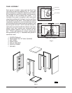
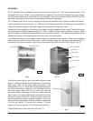
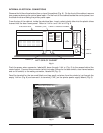
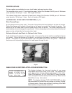
INTERIOR FINISH DETAILS
Plates are provided on the top front of the coil and fan section. Move the plates up to cover the holes
on top of the coil and fan section. Run a bead of silicone sealant all around the coil and fan section,
between its stainless steel structure and the foamed walls. Install the cover for the coil and fan section
using the six wing bolts, supplied. The square openings should be placed in front of the fan units —
louvers, in front of the coil. Fans will not start if the cover is not in its proper position.
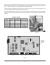
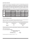
INSTALLATION OF REMOTE ALARM (
OPTIONAL)
The Chiller provides a connection for a remote alarm that operates when the buzzer sounds on
completion of a chill cycle. This output is a set of normally open relay contacts which close when an
alarm occurs. Connections are made to terminals 5 and 6 located in the junction box on the roof per
the wiring diagram and these restrictions:
1. Maximum remote alarm rating: 120V at 2 amps resistive or 100 watt incandescent lamp.
2. Connection must be made with 600 volt insulated wire suitable for supply voltage. Do not use bell
wire, lamp cord or similar type wire.