


22
166240004
12/1/94
Rev 3/4/96
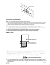
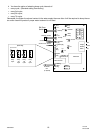
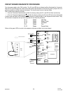
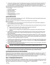
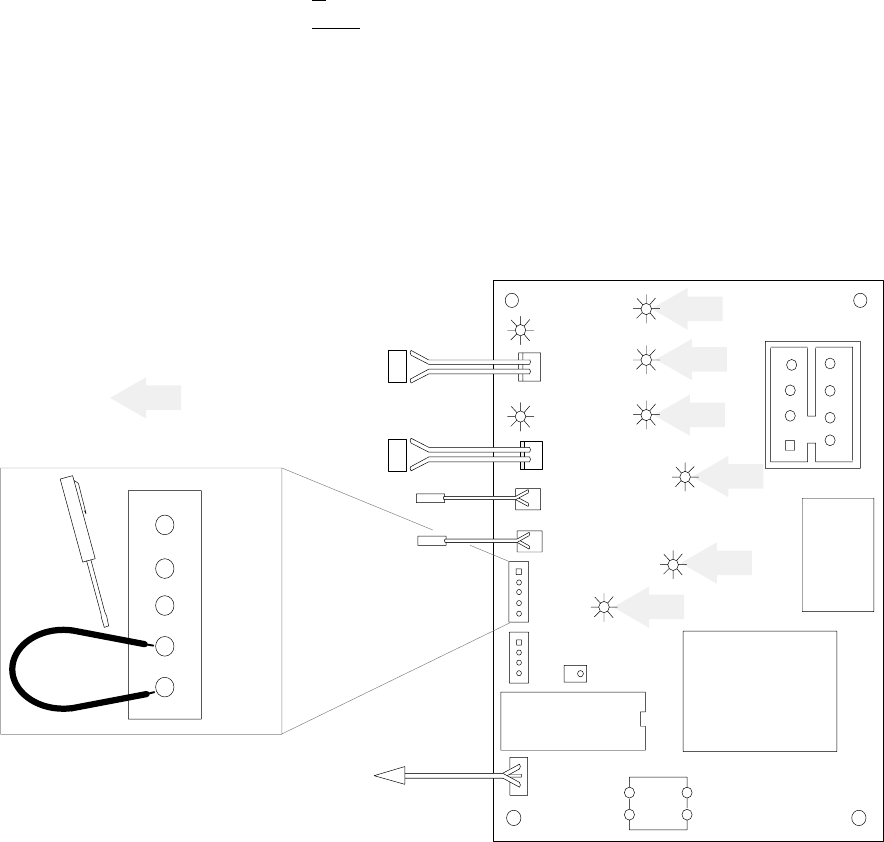
CIRCUIT BOARD DIAGNOSTIC PROCEDURE
Turn the power switch to the “ON” position. The D-5 red LED (error indicator) will be illuminated for 2 seconds.
After the D-5 red LED goes out, short across the bottom two terminals of the Test Plug with a jumper wire or a
pocket screwdriver and then remove the jumper. The circuit board is now in the test mode.
One of these two conditions will exist:
S If the Ice Thickness Potentiometer is within the factory setting the D-5, red LED will flash continiously.
S If the Ice Thickness Potentiomater is not
within the factory setting, the D-5 red LED will not be illuminated.
In either case the Green LED indicators will illuminate for 2 seconds each in the sequence shown below. They
will continue to sequence until you turn the power off and stop the procedure.
D-11 Green Hot Gas
D-12 Green Water Pump
D-14 Green Contactor
D-6 Green Fan
D-15 Green Dump Valve
Failure of the green LED’s to cycle in this sequence indicates a defect in the circuit board.
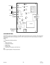
YL
YL
RH Evap.
Water
Dump
Valve
Contactor
Water
Pump
1
3
5
7
2
4
Voltage
Selector
Switch
GR
LH Evap.
Condenser
plug
Suction plug
Test
Plug
Options
Plug
Adjustable Ice
Thickness Pot.
Micro Processor
Stacking
Cable
Plug
Manual
Harvest
Switch
Transformer
To Stacked
Unit
(if required)
Fan
GR
RD
Error
Condenser Sensor
Suction Line
Sensor
N
S
N
S
RH Evap. Switch
LH Evap. Switch
6
8
DĆ15
DĆ13
DĆ14
DĆ12
DĆ10
Hot Gas
DĆ11
DĆ6
DĆ5
White
Brown
Test
Plug
LED Indicators