


26
166240004
12/1/94
Rev 3/4/96
2. Water supply to the product is correct and flow over the evaporator is correct.
3. Cuber refrigerant charge is correct.
4. TXV sensing bulb is properly located and secured to the suction line and correctly insulated.
5. Hot gas valve(s) are not leaking and/or seeping through.
Starving TXV - Product Symptoms
1. Suction pressure lower than normal for the operating conditions.
2. Ice production lower than normal and/or none.
3. Ice pattern on evaporator (if any) thin at top and thick at bottom.
Flooding TXV - Product Symptoms
1. Ice production lower than normal and/or none.
2. Suction pressure stabilizes at higher than normal pressure for operating conditions. Suction pressure does
not modulate and may start to slowly rise.
3. Ice pattern will be very heavy at the bottom and thin at the top of the evaporator. Product may not enter
harvest cycle because of higher than normal suction line temperature.
IMPORTANT: Frost on the suction line may be normal on medium temperature refrigeration equipment.
Frost should be considered a red flag, long run times will normally produce some type of frost pattern.
Before checking the sealed refrigeration system, the external conditions that could lead to frost follow:
1. Dirty condenser
2. Dirty condenser fan blade
3. Improper air clearance around Cuber
4. Loose TXV bulb mount
5. Poor water flow over evaporator
6. Ventilation problems
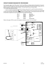
The expansion valves used on Cornelius “I” series ice equipment have special super heat settings and bulb
charge designed for the product load and HP 62 refrigerant. Should the need arise to replace this or any refrig-
erant components, be certain to use only components recommended by Cornelius for the model of the Cuber
being serviced. Use of nonapproved components will compound system difficulties and may void product war-
ranty.
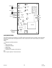
WATER REGULATING VALVE
The water regulating valve is used on water-cooled cubers only. The valve is installed in the condenser outlet
water line. It’s function is to control the proper operating head pressure by regulating the amount of water flow-
ing through the condenser. The valve is adjustable and factory set to maintain condenser discharge water tem-
perature @ 108/112_F (42-44_C). Setting the water regulating valve to maintain discharge water temperature
eliminates the need to enter the sealed refrigeration system. When checking the valve, the water temperature
should be taken as close to the condenser discharged as possible. The water temperature will equate to operat-
ing head pressure of approximately 310 PSI (21.1 BAR).
Should adjustment be required, the valve has an adjustment stem on the top of the valve. After allowing the
cuber to operate for 10 minutes in the ice– making mode to balance the system, turning the adjusting stem CW
will increase the discharge water temperature, and CCW will decrease the discharge water temperature.
The water regulating valve must close off condenser water flow completely during the “hot gas” harvest cycle.
There should be no discharge water flowing out of the condenser during the harvest cycle. Should the valve fail
to close during the harvest mode, the condenser will continue to condense the compressor discharge vapor
needed for the harvest cycle and this will result in long harvest times.
Also discharge water temperature below 108_F /112_F will result in long harvest times.
Leaking (bypassing) water regulating valves are normally the result of scale build-up on the valve diaphragm
and the valve should be flushed, not replaced. To flush the valve, open the adjusting stem wide open CCW (or
force the valve spring up with a screwdriver), open and close the water supply to the condenser resulting in the
flushing action. Should this not correct the problem, replace the valve diaphragm. This can be done without en-
tering the sealed refrigeration system.
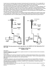
Damage to the water regulating valve may also be caused by water hammer. Water hammer will result from the
condenser inlet and outlet water lines being reversed or defective valve stops in the water supply line. Proper
installation of water–cooled equipment should always include an anti-water hammer standpipe in the supply inlet
line as close to the cuber as possible.