


25
166240004
12/1/94
Rev 3/4/96
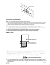
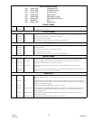
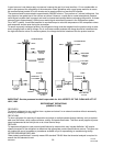
VOLTAGE SELECTOR SWITCH
1. Selector bar in center position, switch is open. Product is inoperative.
2. Selector bar in down position, selection is for 115 VAC.
3. Selector bar in up position, selection is for 230 VAC.
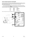
STACKING CABLE
When stacking the “I” series cuber the connecting cable (connecting the two (2) circuit boards) will allow: the
bottom Unit to shut off on the full bin signal (or any error code), the top Unit will then finish the cycle it is in and
shut down. The “I” series should never be stacked more than two high.
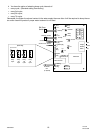
Sensor [Thermistor] Diagnosis
Sensors
Condenser or suction line – Turn Cuber power switch OFF. Disconnect sensor plug from board. Use digital
multimeter set for D.C. Voltage. Turn power switch ON. Connect leads of meter across the two pins of the sen-
sor being checked. Meter should read 2.5 VDC0.2 output voltage from the board. If voltage is not correct, re-
place the circuit board.
Should the cuber operation indicate there may be a fault in the sensor [thermistor] or the control board cir-
cuit proceed as follows.
1. Using a good multimeter, check the control board sensor output voltage.
2. If voltage checks are correct do the following:
A. Disconnect the suction line sensor (brown lead) from the control board.
B. Install the special test cord* to the control board and reinstall the sensor to the test cord terminals.
C. Connect the multimeter (set on VDC - milli-volts) to the test cord leads.
D. Operate the cuber in the freeze cycle.
3. As the suction line temperature decreases the milli-volt reading will increase.
4. Sensor Shorted – milli-volt reading will cease to increase and will remain steady indicating a shorted sen-
sor.
5. Sensor Open – The voltage reading will indicate the control board output voltage of 2.5 VDC.
6. Should step 4 or 5 occur during this test, the sensor will require replacement.
* Special test cord, part # 164984009, may be ordered through the Service Department.
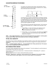
7. Condenser Sensor (white leads) – self-contained air-cooled only – water cooled and remote systems
use a resistor plug on the control board.
Complete the sensor and multimeter connections as described in
2- B, C, D
8. Shorted sensor – a steady low milli-volt reading will be recorded. The reading will not change.
9. Open sensor – the multimeter will record control board output voltage of 2.5 VDC.
10. Should sensor (thermistor) pass the voltage test proceed to the control board diagnosis for LED sequence
(see page 22).
NOTE: The sensor controls the condenser fan cycling from 88/100 degree Fahrenheit. Thus any de-
fects in the condenser circuit will effect the fan cycling rate.
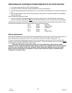
CONDENSER FAN CYCLING CONTROL
The condenser fan on air-cooled cubers is cycled by the circuit board. The condenser sensor signals the circuit
board when the condenser temperature reaches 100°F (38°C) the fan starts and continues to run until the tem-
perature is reduced to 88°F (31°C).
NOTE: There is no pressure control used to cycle the fan motor on intergal condensor unit.
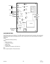
THERMOSTATIC EXPANSION VALVES
The following suggestions for diagnosis of automatic Thermostatic Expansion Valve (TXV) are given with the
understanding that the following have been checked and are correct and/or have been corrected prior to pro-
ceeding.
1. The condenser and fan blade are clean and have proper operating conditions.