


77
166240004
12/1/94
Rev 3/4/96
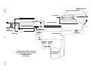
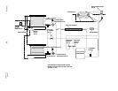
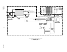
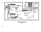
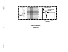
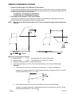
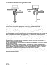
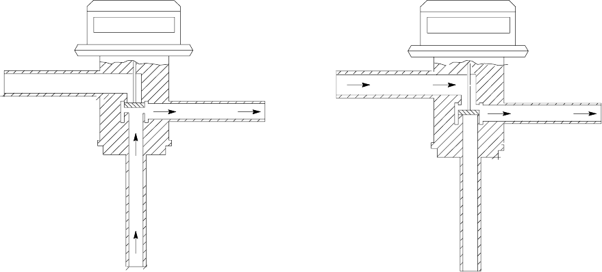
HEAD PRESSURE CONTROL [HEADMASTER]
discharge
receiver
condenser
above 70°F
normal
discharge
receiver
condenser
below 70°F by-pass
The Cornelius “I” series remote systems use an Alco Head Pressure Control, normally referred to as a head-
master. This control is mounted in the remote condenser with a fan cycling control switch. Using both these
controls gives the system positive operation under a wide range of condensing temperatures.
The cycling control starts the fan at 270 PSI and stops it at 205 PSI allowing a positive efficient operation at the
high temperature operating ranges.
The headmaster controls the operation when the condensing temperature drops below 70°F. The “I” series re-
frigerant charge is HP - 62 [R - 404A] and the headmaster dome charge setting is 200 PSI of nitrogen pressure
making it stable under the low temperature operating range down to - 20°F.
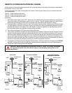
The normal flow pattern through the headmaster is from the condenser port to the receiver port. When this flow
pattern is unable to maintain a receiver outlet pressure equal to or above the dome pressure setting of the
valve, the dome pressure will force the valve portage to change closing the condenser port and opening the by-
pass port from the compressor discharge line. This allows the high pressure vapor from the discharge port to
“buck” the receiver pressure back up. With the condenser port closed, the refrigerant is backed up in the con-
denser, basically reducing the condenser size, assisting in maintaining the discharge portage flow and increas-
ing the head pressure.
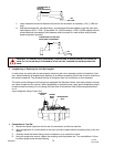
Remember, sense of touch to the lines of the headmaster will determine the flow path the headmaster is in,
condenser to receive, or bypass to receiver.
High side gauge installed at the receiver outlet valve will determine if the headmaster is functioning to maintain
the proper operating pressure.
In the event the control appears to be “stuck in bypass”, the pressure drop across the headmaster must be
measured. With a gauge installed at the receiver outlet valve and the high side service valve, the pressure dif-
ference at these two points must be less than the 15 PSI. The three most common causes of an excessive
pressure drop are shortage of refrigerant, kinked remote lines, and excessive line length.
Eliminate refrigerant shortage first. Add refrigerant in two-pound increments (not to exceed six pounds) to
determine if it corrects the pressure drop. If pressure drop is not corrected, inspect line set for sharp bends or
kinks and correct as required. If adding refrigerant does not correct continued (bypass) condition and line set is
not damaged, replace headmaster.