10
SECTION 2: INSTALLATION/OPERATION INSTRUCTIONS
INSTALLATION INSTRUCTIONS
PLUMBING THE DISHMACHINE: All plumbing connections must comply with all applicable local, state, and national plumb-
ing codes. The plumber is responsible for ensuring that the incoming water line is thoroughly flushed prior to connecting it to
any component of the dishmachine. It is necessary to remove all foreign debris from the water line that may potentially get
trapped in the valves or cause an obstruction. Any valves that are fouled as a result of foreign matter left in the water line, and
any expenses resulting from this fouling, are not the responsibility of the manufacturer.
CONNECTING THE DRAIN LINE: The drain for the dishmachine is a gravity discharge drain. Remove the overflow strainer
stopper from the tub and the unit will drain itself. There must also be an air gap between the machine drain line and the floor
sink or drain. If a grease trap is required by code, it should have a flow capacity of 5 gallons per minute.
WATER SUPPLY CONNECTION: Ensure that you have read the section entitled “PLUMBING THE DISHMACHINE” above
before proceeding. Install the water supply line (3/4” pipe size minimum) to the end of the Y-strainer. It is recommended that a
water shut-off valve be installed in the water line between the main supply and the machine to allow access for service. The
water supply line is to be capable of 25 PSI “flow” pressure at the recommended temperature indicated on the data plate. In
areas where the water pressure fluctuates or is greater than the recommended pressure, it is suggested that a water pressure
regulator be installed. The Model 10 does not come with water a pressure regulator as standard equipment.
Do not confuse static pressure with flow pressure. Static pressure is the line pressure in a “no flow” condition (all valves and
services are closed). Flow pressure is the pressure in the fill line when the fill valve is opened during the cycle.
It is also recommended that a shock absorber (not supplied with the dishmachine) be installed in the incoming water line. This
prevents line hammer (hydraulic shock), induced by the solenoid valve as it operates, from causing damage to the equipment.
PLUMBING CHECK: Slowly turn on the water supply to the machine after the incoming fill line and the drain line have been
installed. Check for any leaks and repair as required. All leaks must be repaired prior to placing the machine in operation.
ELECTRICAL POWER CONNECTION: Electrical and grounding connections must comply with the applicable portions of the
National Electrical Code ANSI/NFPA 70 (latest edition) and/or other electrical codes.
Disconnect electrical power supply and place a tag at the disconnect switch to indicate that you are working on the circuit.
Refer to the data plate for machine operating requirements, machine voltage, total amperage load and serial number.
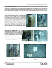
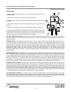
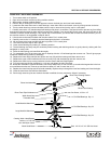
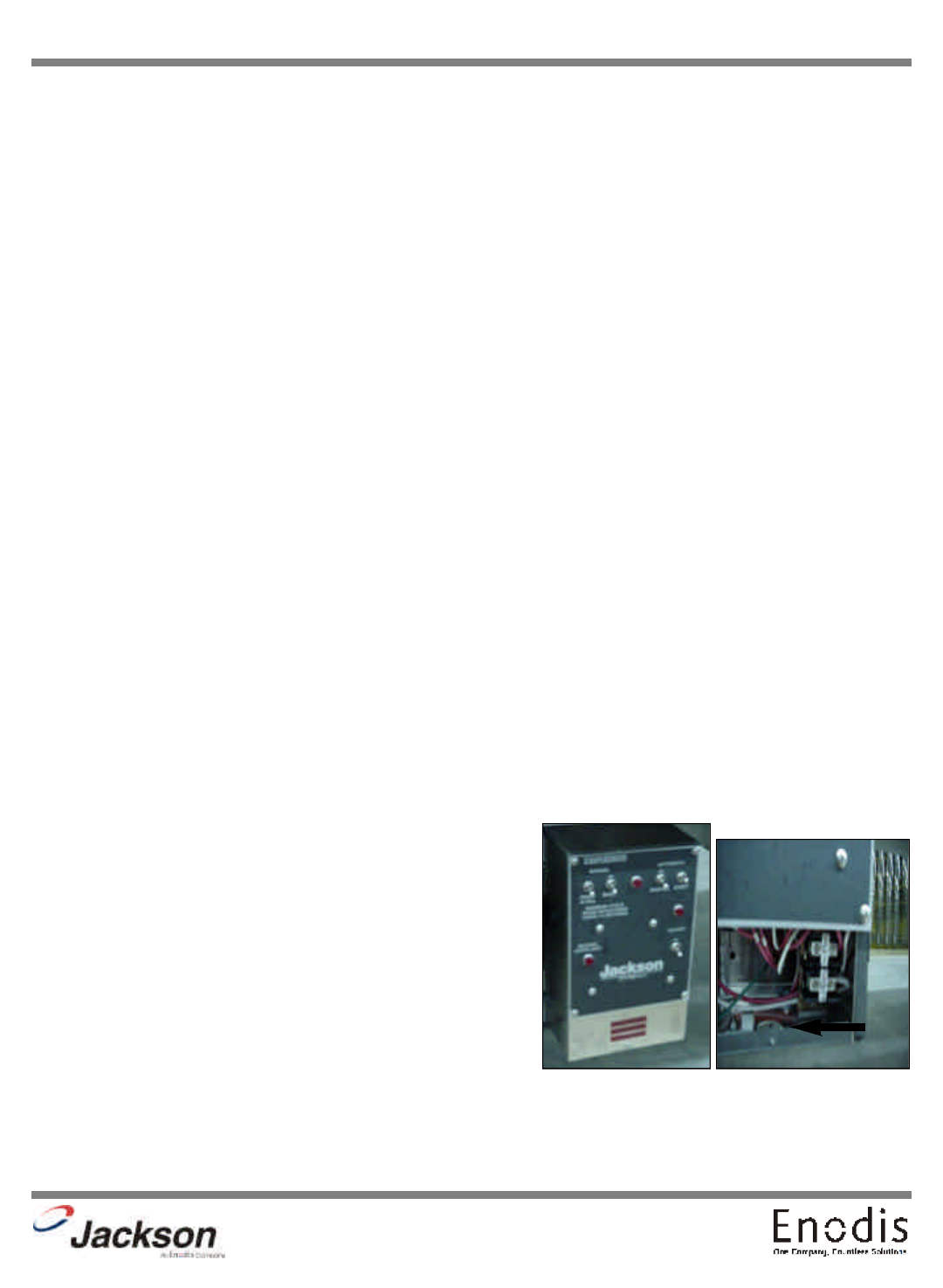
To install the incoming power lines, first remove the lower control box cover (Fig. 15). Next, run the power lines through the
hole located in the bottom of the control box to the terminal board inside (Fig. 16). This board is accessible by removing the
lower cover plate on the control box. Attach lines (L1 and L2 (L3 for three phase)) on the terminal block at the lower front right
corner. There is no neutral wire on this machine. There is a grounding lug inside the control box on the bottom left. Be sure all
connections made are tightened properly. It is recommended that “DE-OX” or another similar anti-oxidation agent be used on
all power connections.
VOLTAGE CHECK: Ensure that the power switch is in the OFF position
and apply power to the dishmachine. Check the incoming power at the
terminal block and ensure it corresponds to the voltage listed on the data
plate. If not, contact a qualified service agency to examine the problem.
Do not run the dishmachine if the voltage is too high or too low. Shut off
the service breaker and mark it as being for the dishmachine. Advise all
proper personnel of any problems and of the location of the service break-
er. Replace the lower cover and tighten down the screws.
(Fig. 15) (Fig. 16)


