


19
SECTION 4: SERVICE PROCEDURES
FUNCTION OF SWITCHES, CIRCUIT BREAKER & INDICATING LIGHTS\REPLACEMENT OF SWITCHES
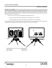
FUNCTION OF SWITCHES, CIRCUIT BREAKER & INDICATING LIGHTS:
CIRCUIT BREAKER: Rated 15 amps, controls power to the control circuit only, I.E. timer, relays, solenoid valve, water level con-
trol and motors. The circuit breaker does not cut off power in the control box at incoming terminal board and rinse heater relay
contacts. Power is still applied to them when the circuit breaker is in “off” position.
MASTER SWITCH: The switch interrupts all power going to the control circuit, this means that all switches on control panel are
inoperable until master switch is turned “on”.
START SWITCH: This switch controls the timer motor through two circuits (see electrical diagram) it is a three-position switch, up
position = start, middle position = off, down position = start. To start, flip switch toggle in either up or down position; indicating light
in center of panel will light verifying automatic cycle has started. After cycle ends and you are ready to start a new cycle, flip toggle
to opposite position.
CYCLE LIGHT: This light comes on only when automatic cycle is in progress and extinguishes when cycle is complete.
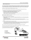
MANUAL WASH SWITCH: The switch is used to by-pass the timer and operate the wash pump manually. The wash pump will run
as long as this switch is “on”. The prime purpose of this switch is to extend the wash period for extremely soiled dished before putting
them through the normal automatic cycle. It may also be used as an emergency back-up should the timer ever fail to operate. The
required wash time is indicated on the control panel (front).
RINSE/FILL SWITCH: This switch is spring loaded and must be held in its up position to operate. When the switch is operated,
water is allowed to fill machine through the rinse heads. It may be used as an emergency back-up in case of timer failure for rins-
ing dishes. The required rinse time is indicated on the front control panel.
HEAT SWITCH: This switch applies power to the heat circuits which are composed of automatic control devices that turn heaters
on and off to maintain required temperatures.
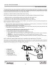
REPLACEMENT OF SWITCHES IN CONTROL PANEL:
HEAT LIGHT: This indicating light remains lit all the time the heat switch is on.
There are five switches installed in the control box cover panel. These are the start, master, manual wash, rinse/fill and heater
switches.
Before working on the machine, it is important that power be turned off at the customer’s circuit breaker to prevent the possibility of
electrical shock, trip breaker to “off” position.
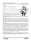
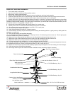
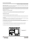
Remove control panel from the control box by removing the four screws holding it in place. Hang the control panel using the two
right hand upper and lower screw receptacles on the control box with backside of panel facing outward. The five switches are mount-
ed in individual round holes with a keyway. By using a pair of pliers, or open end wrench, it is possible to loosen the inside nut
enough to allow the outside nut holding the switch to be removed by fingers. Push switch out of hole.
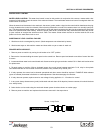
If a switch is found to be defective, replacement can be achieved by placing the new switch next to the old one. To make the new
switch is not upside down, line up with the keyways. Transfer wires one at a time to the new switch. If this is not practical, pull wires
off, one at a time and tag them for proper replacement.
Put switches back into panel, make sure switch protrudes through panel proper-
ly, tighten both nuts, and replace control panel on control box. Power can now be
applied to the dishmachine and run through cycles checking all operations.
1. Connection terminals
2. Inside nut
3. Panel plate
4. Outside nut
5. Bar or toggle handle
1
2
3
4
5