


21
SECTION 4: SERVICE PROCEDURES
RINSE TANK HEATER SYSTEM
The rinse tank heater system is electrically connected in the circuit and is controlled by a heat switch (mounted on the front panel)
and a thermostat (mounted near the right front leg underneath) which activates the coil on the heat relay, mounted in the control
box. When higher temperature is required, power is applied to the heaters (mounted on the right end of built in boosters) when the
contacts of the heat relay are closed. Should the rinse tank thermometer read either too high or too low, follow checkout below.
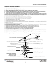
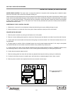
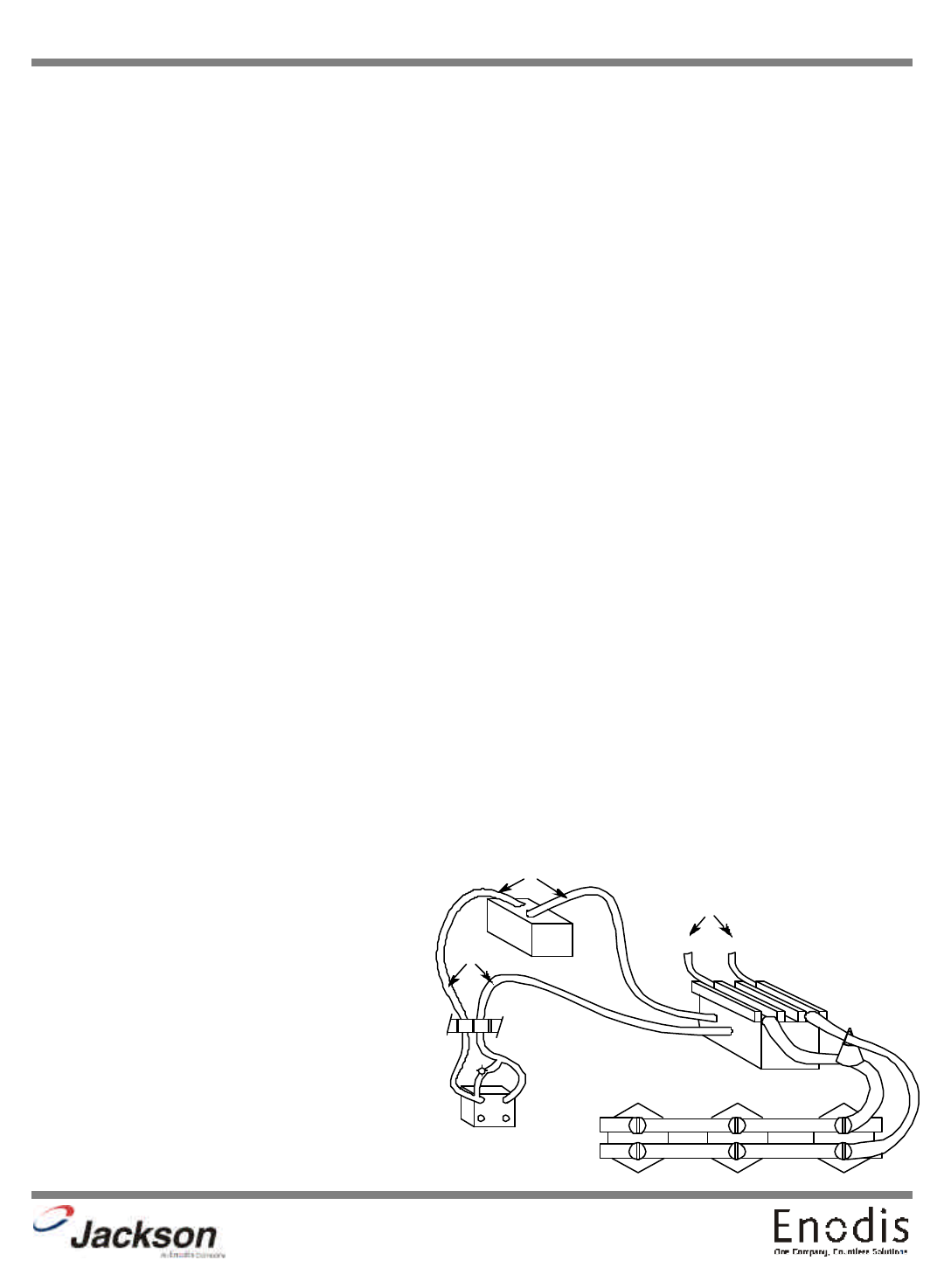
CHECKOUT OF HEATER SYSTEM FOR RINSE TANK (Refer to drawing)
NOTE: THE FOLLOWING CHECKOUT SHOULD BE DONE BY A QUALIFIED SERVICE PERSON OR ELECTRICIAN.
1. If temperature is too high, adjust thermostat using thermostat instructions in this manual.
2. If temperature is too low, adjust thermostat using thermostat instructions in this manual then:
a. Turn off power to machine by tripping customer circuit breaker to “off” position.
b. Remove lower cover plate on control box (held by a single screw).
c. Make sure rinse temperature is below 180°F (preferably about 140°F).
d. Re-apply power, turn on master switch and observe heat relay (2 pole mounted at the lower left inside control box) letter “C”
figure 1 as heat switch is turned on and off several times.
NOTE: ELECTRICAL POWER STILL APPLIED, SO BE CAREFUL. (See instructions in manual for removing control panel front.
Refer to replacement of switch in control panel.)
1. If heat relay contacts do not close: With heat switch on:
a. Check power supply at Position 1 on terminal board X. Voltage should be 208-230 VAC. If not, check customer’s breaker, if
defective, replace.
b. Check position 2, voltage should be 0 volts. If not, check thermostat, adjust per instructions, check master and heat switch, if
any items are defective, replace.
c. Check position 3, there should be 208-230 Volts there. If not, check wiring for breaks or poor connections.
d. If voltage is being applied to Positions 1 and 3 and the relay doesn’t operate, it should be replaced, coil on relay is probably
open.
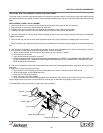
2. To determine if elements are working, if heat relay does not close:
a. There is an insulated movable bar on the heat relay across the top of the two contacts. With an insulated probe, depress the
bar and observe the rinse thermometer, the temperature should rise noticeably in a minute or two. If it move VERY slowly, it
would indicate that one element is defective. If it moves consistently higher at a steady rate, elements are okay.
b. Check voltage at position 4. There should be 208-230 Volts. If not, check wiring.
NOTE: A CHECK WITH AN AMP PROBE (POSITION E), IF AVAILABLE, WOULD BE HELPFUL AT THIS POINT.
Clamp probe on single wire between heat relay and heater elements. The elements together on a single phase should draw 30
amps, one element will draw only 10 amps. Replace element if found inoperative.
3. If relay is closed, but elements do not heat, use same
general methods used in step 2 above for checkout.
B
A
C
3
1
X
2
L1
L2
E
D D D
6 19
A - Heater Switch
B - Thermostat
C - Heater Relay
D - Rinse Tank Heaters
E - Amprobe Test Position
X - Terminal Board (9 terminals)