


NOTE: THE INSTRUCTIONS PROVIDED HEREIN, UNLESS OTHERWISE SPECIFIED ARE FOR THE DISHMA-
CHINES ONLY. THERE ARE SEPARATE DIRECTIONS FOR THE GAS BOOSTER.
VISUAL INSPECTION: Before installing the unit, check the container and machine for damage. A damaged container is an indi-
cator that there may be some damage to the machine. If there is damage to both the container and machine, do not throw away
the container. The dishmachine has been inspected and packed at the factory and is expected to arrive to you in new, undam-
aged condition. However, rough handling by carriers or others may result in damage to the unit while in transit. If such a situ-
ation occurs, do not return the unit to Jackson; instead, contact the carrier and ask them to send a representative to the site to
inspect the damage to the unit and to complete an inspection report. You must contact the carrier within 48 hours of receiving
the machine. Also, contact the dealer through which you purchased the unit.
UNPACKING THE DISHMACHINE: The machine should be unboxed and removed from shipping pallet prior to being installed.
Open the front door and remove all of the packing materials. Once unpacked, ensure that there are no missing parts from the
machine. This may not be obvious at first. If it is discovered that an item is missing, contact
Jackson immediately.
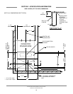
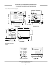
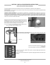
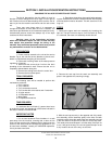
LEVEL THE DISHMACHINE: The dishmachine is designed to operate while being level. This is
important to prevent any damage to the machine during operation and to ensure the best results
when washing ware. The unit comes with adjustable bullet feet, which can be turned using a pair
of channel locks or by hand if the unit can be raised safely. Ensure that the unit is level from side
to side and from front to back before making any connections. You will be able to adjust the over-
all height of the unit by turning the bullet feet from between 75-1/2” to 76-1/2”.
PLUMBING THE DISHMACHINE: All plumbing connections must comply with all applicable local, state, and national plumb-
ing codes. The plumber is responsible for ensuring that the incoming water line is thoroughly flushed prior to connecting it to
any component of the dishmachine. It is necessary to remove all foreign debris from the water line that may potentially get
trapped in the valves or cause an obstruction. Any valves that are fouled as a result of foreign matter left in the water line, and
any expenses resulting from this fouling, are not the responsibility of the manufacturer.
Water hardness should be a maximum of 6 grains per gallon. Harder water should be treated prior to using the machine. Iron
in the water supply can cause staining. A filter designed to remove iron from the supply water is highly recommended for sup-
plies in excess of 0.1 ppm (parts per million).
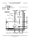
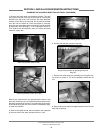
CONNECTING THE DRAIN LINE: The drain for the models covered in this
manual are gravity discharge drains. All piping from the machine to the drain
must be a minimum 1 1/2” NPT and should not be reduced. There must also be
an air gap between the machine drain line and the floor sink or drain. If a grease
trap is required by code, it should have a flow capacity of 30 gallons per minute.
WATER SUPPLY CONNECTION: Ensure that you have read the section enti-
tled “PLUMBING THE DISHMACHINE” above before proceeding. The supply
water temperature must meet the minimum requirements listed on the machine
data plate. Install the water supply line (3/4” pipe size minimum) to the dishma-
chine line strainer. It is recommended that a water shut-off valve be installed in
the water line between the main supply and the machine to allow access for ser-
vice. The water supply line is to be capable of 25 PSI “flow” pressure at the rec-
ommended temperature indicated on the data plate.
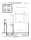
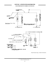
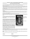
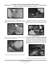
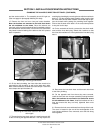
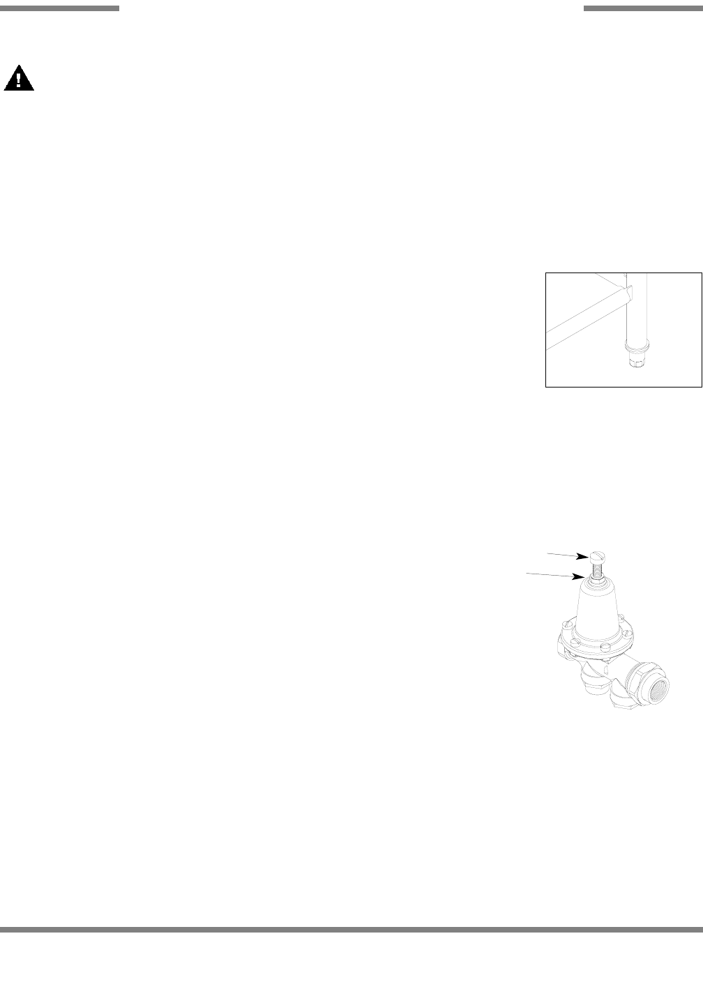
If the water level is too low or too high, check the incoming water pressure. It should be 20 ± 5 PSI. Too high of pressure results
in too much water; too low of pressure results in too little water. To adust the regulator, loosen the nut at the top, this will allow
you to screw or unscrew the adjustment. With a screwdriver, turn the adjuster clockwise to increase pressure or counter clock-
wise to decrease it.
Do not confuse static pressure with flow pressure. Static pressure is the line pressure in a “no flow” condition (all valves and
services are closed). Flow pressure is the pressure in the fill line when the fill valve is opened during the cycle.
AJ-44C Series Technical Manual 7610-001-76-22
Issued: 03-21-2006 Revised: N/A
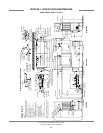
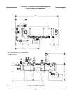
SECTION 2: INSTALLATION/OPERATION INSTRUCTIONS
INSTALLATION INSTRUCTIONS
30
Adjusting screw
Locking nut
Incoming Plumbing Connection
Frame with Adjustable Foot