


ELECTRICAL:
WARNING: Electrical and grounding connections must comply with applicable portions of the National Electrical Code
ANSI / NFPA 70 (latest edition) and/or other electrical codes.Disconnect electrical power supply and place a tag or lock
at the disconnect switch to indicate that you are working on the circuit.
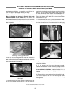
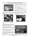
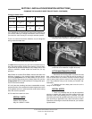
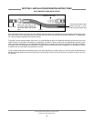
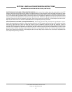
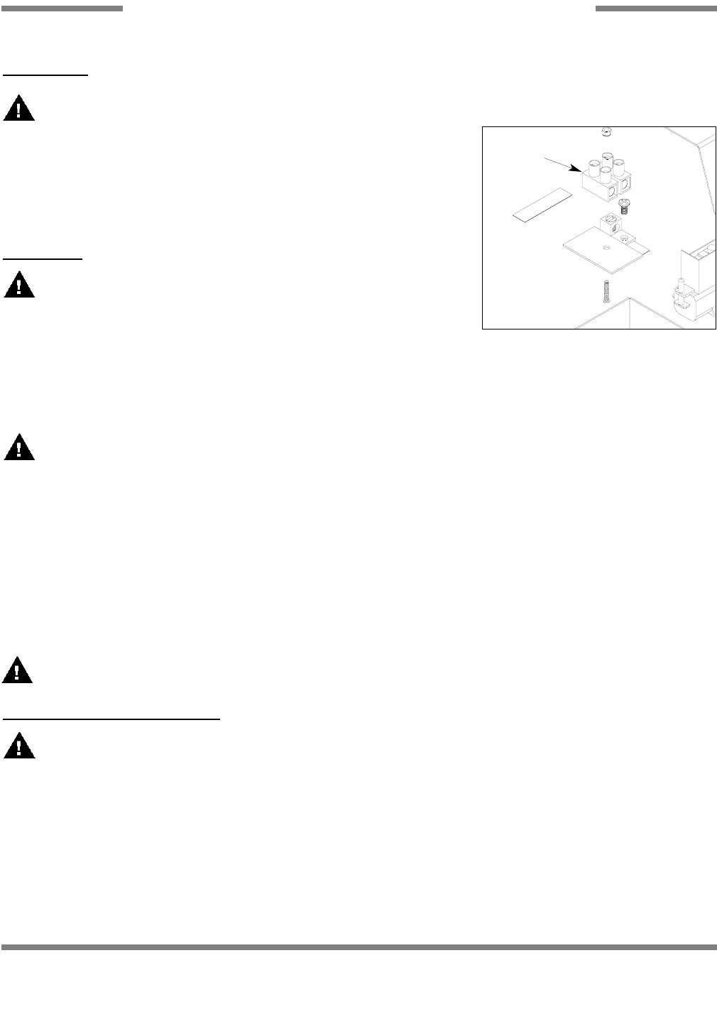
To connect the incoming power, run the conduit for power wires through the open
hole in the back of the control box. Connect the power wires to the terminal block as
it is labeled (L1 and L2). Run the ground wire to the grounding lug marked “GND”.
Tight connections and conduit nuts and close the control box by putting the cover on
and securing with the 10-32 screws.
OPERA
TION:
WARNING: The heat exchanger used in the D226 Booster system is a pres-
sure vessel with very precise operating parameters. Safety equipment such as
relief valves should never be tampered with or disabled. These devices are meant to
protect the equipment and the operator from harm, damage and death.
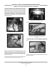
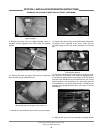
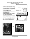
1. Ensure that water, steam and any condensate drains are connected to the booster.
2. Start the water flow first, open the condensate drains and then begin steam flow.
3. On the control box, press the power switch and put it in the ON position. The power light should illuminate.
The unit should run normally now.
WARNING: Do not shock the system by applying the steam before the water. This can cause damage to the booster.
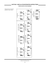
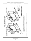
The following explanation describes the operation of the D226 Booster.
NOTE: This explanation assumes that water and steam have been connected to the machine.
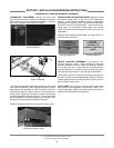
1. When the power switch (S1) is placed in the ON position, power is provided to both the power light (E1) and the thermostat
(TS1).
2. The thermostat (TS1) will close when the water falls below the minimum setpoint, energizing the steam solenoid light (E2)
and the steam solenoid (FS1).
3. The steam solenoid (FS1) will remain open, allowing steam into the booster, until the water temperature reaches the desired
temperature. At that point, the thermostat (TS1) will open, de-energizing the steam solenoid (FS1) and the steam solenoid light
(E2).
IMPORTANT: Please remember that all of the components in the control box are under line voltage (208-240 volts).
Under no circumstance is the control box cover to be removed or opened during normal operations!
SHUTDOWN (FOR SER
VICE ONLY):
WARNING: The D226 Booster is designed to heat water to a minimum of 180°F and is extremely hot during operations.
Advise personnel of the dangers associated with touching booster components as burns or severe injury can occur.
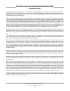
1. Turn the power switch to the OFF position. The power light should extinguish.
2. Secure steam flow to the unit.
3. Secure water flow.
4. Close the condensate drains as required by procedure and/or code.
5. Do not attempt to clean, wipe down or perform any maintenance on the booster until it has been given a generous amount
of time to cool down.
AJ-44C Series Technical Manual 7610-001-76-22
Issued: 03-21-2006 Revised: N/A
SECTION 2: INSTALLATION/OPERATION INSTRUCTIONS
D226 STEAM BOOSTER INSTALLATION & OPERATION INSTRUCTIONS (CONTINUED)
43
10
Terminal Block
D226 Conrtol Box