


AJ-44C Series Technical Manual 7610-001-76-22
Issued: 03-21-2006 Revised: N/A
SECTION 2: INSTALLATION/OPERATION INSTRUCTIONS
CHANGING THE AJ-44CE/CS DIRECTION OF TRAVEL (CONTINUED)
39
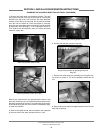
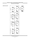
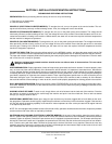
Conveyor Switch Chart:
The chart above lists the conveyor switches and their func-
tions, depending on the direction of travel for the machine. As
you can see, when you change the direction of the conveyor,
you must also alter the way the conveyor switches operate.
There is no need to remove the switches, only to change the
wiring inside the heater box.
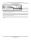
34. Note: Before beginning any part of this maintenance evo-
lution that deals with the wiring of the machine, ensure that it
is performed by qualified technicians only. Always refer to the
machine schematic, located inside the control box, for any
questions.
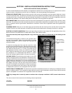
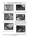
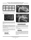
Wash Switch #1 and the Rinse Switch need to have their wire
positions changed on the terminal board pictured above.
Locate the gray/yellow wire for Wash Switch #1 (do not con-
fuse it with the gray/yellow wire for Wash Switch #2) and the
orange/yellow wire for the Rinse Switch. Exchange their posi-
tions on the terminal board.
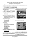
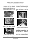
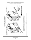
35. Verify that the plumbing has been reassembled correctly
and that the hole cover weldment has been replaced and none
of the gaskets are torn or pinched as this could lead to leaking
when the machine operates.
35. Re-install the heater box cover.
SPECIAL PARTS
Gasket, Rinse Injector:
Mfg. No.: 05330-111-42-81
AFTER MAINTENANCE ACTIONS
1. Reconnect the incoming water and drain lines and
then restore power to the unit. Run the unit for at least 1/2
hour to ensure there are no leaks. Test the unit with an empty
rack to ensure that it pulls the rack all of the way through the
unit. If any problems arise you can contact your Jackson rep-
resentative.
2. Replace the front dress panel once the unit is
ready for service again.
SPECIAL NOTES
1. There is a possibility that you may be required to
shorten or lengthen the conduit and wire lengths for the inlet
solenoid on the rinse plumbing once it is moved. This work
should be performed by qualified technicians who will do the
work according to applicable local, state and national codes.
Questions concerning this should be directed to your Jackson
representative.
Unit
Direction
Switch #1 Switch #2 Switch #3
Left to Right
Wash Switch
#1
Wash Switch
#2
Rinse Switch
Right to Left Rinse Switch
Wash Switch
#2
Wash Switch
#1
Terminal board inside the heater box
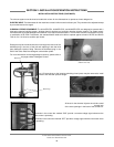
Incoming plumbing assembly for a Right to Left machine
(note hole cover weldment in upper left corner)
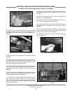
Incoming plumbing assembly for a Left to Right machine
(note hole cover weldment in lower right corner)